Category: Making

  • Memories of Skateboarding and Nostalgic Assembly of a Re-Issued Mike McGill Powell-Peralta Skull & Snake Skateboard

    complete-mcgill-skateboard-top-and-bottom.jpg
    My Mike McGill Pro Model “Skull and Snake” Re-Issue Series 5 by Powell-Peralta, Complete with Gullwing Pro III Trucks and Sector Nine Nineballs Wheels.

    This is a long read that combines autobiography, nostalgia, memory, and instructions. Visitors here might find it interesting and informative. My students might use it as a model for some of their own multimodal writing about memory, processes, instructions, and reflection.

    While it has been over 25 years since I last rode a skateboard with my hometown friends, I recently felt drawn to the 7-ply deck once again and decided to assemble a board similar to my second skateboard–a 1990 Powell-Peralta Mike McGill pro board with VCJ’s Skull & Snake graphics, fish shape, nose and tail kicks, natural wood grain with Gullwing Pro III trucks (red), and Powell-Peralta Rat Bones wheels (neon green).

    Before I got my original McGill deck, I learned to skateboard on a Teenage Mutant Ninja Turtles complete skateboard that my grandparents–Wilma and Papa Gerald–bought for me from the Wal-Mart on Altama Avenue in Brunswick, Georgia (since replaced by a Supercenter about a mile away, and then the original site re-built as a Neighborhood Market a few years ago).

    With the TMNT skateboard, I learned how to balance, turn, and ride on my grandparent’s back car port. At first, I held on to a broom handle to steady myself until I felt confident enough to ride without this support. I don’t think I had a helmet, but I did have pads and wrist guards–the former store bought neon green plastic over black, and the latter used, red, gifted or traded for–I can’t remember.

    I rode and shared the TMNT skateboard with my friends who I paled around with when I stayed at my grandparents. However, I wanted to learn how to ollie and do tricks, but I found this to be next to impossible on the heavy, tank-like TMNT board. This is what began my search for a better board, relying heavily on the photo stories and advertising in magazines such as Transworld Skateboarding and Thrasher, and eventually led to me mail ordering the McGill deck and new hardware (was this a Christmas gift from my grandparents or my folks–again, my memory falters).

    With the new McGill, I continued skating through the beginning of high school, but I drifted away from the sport when I got more interested in books (physics first, science fiction second), computers (Amiga, IBM-compatible PCs, and eventually, Macintosh), and cars (my first being a 1965 Ford Mustang, but always having a soft spot for the small Toyota pickup trucks that I used to deliver auto parts from my family’s business).

    I don’t remember what became of my McGill. I suspect that I gave it to a friend before going to college where I really got into Rollerblading, but my memory fails completely on this point. I hope that I can remember what happened to my old McGill skateboard, not because I want it back, but instead simply to recall that moment in my life’s narrative. Related to this is the fact that I don’t seem to have any photos of me with my skateboard (though I do have a photo of me holding my Rat Bones wheels on Christmas Day). It’s an odd omission in the photographic record of my life of something I considered important to me at that early time in my life.

    hackers-the-plague-mcgill-skateboard.png
    In the film Hackers (1995), The Plague (Fisher Stevens) rides into the NOC on a McGill skateboard while Hal (Penn Jillette) studies the situation.

    My re-interest in skateboarding began when I was watching the film Hackers (1995) in HD. I don’t think it registered with me when I first saw it when it was originally released that the film’s villain, The Plague (Fisher Stevens), rides into his company’s NOC (network operations center) on a McGill skateboard (see above).

    Then, I caught up with my oldest best friend Bert over the phone. He lives in Seattle now, but back in the day, we used to skateboard in his neighborhood. Bert was a much better skater than me. Our conversation drifted back to skateboarding, including the time that he and I were stopped by a cop on our way back from a Hampton Inn construction site. The obese, good ol’ boy police officer asked us questions about what we had been doing and he stopped when he pointed his flashlight on our boards. Bert skated Vision, and I skated Powell-Peralta. The cop took a breath through his teeth and said, “now boys, I’ve done heard things about that POW-ell Per-AL-ta. They’s devil worshipers!” Bert and I smiled and nodded until he let us go on our way back to his house, but it’s a strange encounter that’s stuck with me.

    Our phone conversation encouraged me to begin searching the web for information about my old skateboard. This led me to the Bones Brigade video The Search for Animal Chin (1987), which I shared with Bert via text message. By this point, I was thinking and spending more free time learning more about skating history and its evolution after I had left the sport.

    While I was already burdened by a big research project on computers in science fiction from 1975-1995, which I’m continuing to work on, and the Third Annual City Tech Science Fiction Symposium, which I was organizing, I wanted to give myself something on the horizon to look forward to as a reward for this work. I decided to get the parts to build a new, complete skateboard similar to one that I had to before without breaking the bank, so I turned to eBay after striking out with the major skateboard online retailers and local shops, such as Uncle Funky’s Boards.

    mcgill-skateboard-top-and-bottom.jpg

    While I couldn’t find my original McGill with a natural finish, I did find this brand new, black dipped, Series #5 re-issue on offer by a seller in Puerto Rico. We negotiated a best offer price, and I received it before anything else.

    IMG_20181208_154036.jpg

    I picked up a Gullwing Pro III trucks, wheels, bearings, risers, hardware combo from Raptorunner in Riverside, CA, and I ordered a Powell Peralta Tailbone and Jessup grip tape (and a helmet and pads) from TGM Skateboards in Mount Clemens, MI.

    IMG_20181208_154142.jpg

    My original Gullwing Pro III trucks were cherry red and stood out well against the natural grain of the board. I liked these new 9″, 155mm neon green ones, because they stand out against the black background on the new, black McGill deck. Also, my re-issued McGill deck uses the old truck bolt pattern, so I chose between these (note that the base plate has six bolt holes instead of four–to accommodate both old and new bolt patterns) and Independent Stage 11 169mm trucks. Ultimately, I opted for the Gullwings since I skated with them before.

    IMG_20181208_154216.jpg

    Raptorunner had several different truck, wheel, and hardware bundles. I chose this one, because it had these Sector Nine Nineballs wheels. They aren’t too big (I would have preferred 56mm) and they are real soft (78a), which will be good for the street crusing that I intend to use the skateboard for.

    IMG_20181208_155501.jpg

    To begin my skateboard’s assembly, I began with the Tailbone before applying the grip tape. I clamped the tail guard to the bottom of the deck’s tail and measured to ensure it was centered.

    IMG_20181208_160002.jpg

    Then, I used a small drill bit to lightly mark where I should drill the larger holes for the wood screws that will go through the top of the board into the Tailbone.

    IMG_20181208_160143.jpg

    I used the grip tape shipping tube to support the deck while I was drilling.

    IMG_20181208_160631.jpg

    Powell-Peralta’s instructions for the Tailbone call for a 7/32″ drill bit. Unfortunately, I didn’t have one in this size. I didn’t want to go with a larger hole (1/4″), so I tried the 3/16″ bit. Luckily, this was more than enough room for the wood screws to pass through the board without biting and then go into the Tailbone.

    IMG_20181208_160345.jpg

    Using my earlier marks, I drilled three holes through the deck’s tail. These will be used later for mounting the Tailbone.

    IMG_20181208_160857.jpg

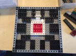
    Before mounting the Tailbone, I applied the Jessup grip tape. I bought 10″ wide grip tape, which is just barely wide enough to give some room for error with the front of the deck. If I had to do over again, I would have opted for the 11″ wide grip tape.

    I wanted the Bones Brigade logo to appear on the top of the deck, so I needed to apply two sections of grip tape–one above it towards the nose and one below it towards the tail. I measured these lengths twice and cut the length of grip tape into two sections allowing some room for error in terms of length. I used the pre-cut edges as the beginning of application above or below the Bones Brigade logo. I slowly lowered and pressed the grip tape to the deck so as to avoid any air bubbles under the tape.

    IMG_20181208_162618.jpg

    With the tape applied, I used the barrel’s edge of a screw driver to draw a scoring line around the edge of the skateboard deck.

    IMG_20181208_162653.jpg

    Then, I used a razor blade held from underneath the board to follow the edge of the board and cut the excess grip tape off along the scoring line.

    IMG_20181208_162821.jpg

    Next, I pressed the grip tape down around the edges of the deck.

    IMG_20181208_162828.jpg

    I ran a rolled up piece of excess grip tape around the edge of the deck to give the grip tape a clean edge all away around.

    IMG_20181208_162906.jpg

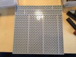
    With the grip tape applied, I used a screw driver to punch through all of the holes in the deck for the trucks and Tailbone.

    IMG_20181208_163309.jpg

    Next, I installed the tailbone by pushing through wood screws and matching them to the holes in the Tailbone.

    IMG_20181208_163305.jpg

    While I had a cordless drill on-hand, I preferred to install these screws by hand. I was afraid of over torquing the screws and losing grip in the Tailbone’s plastic. Installing the screws by hand allows me to feel them dig into the plastic and maintain a secure hold on the Tailbone through the deck without stripping out plastic.

    IMG_20181208_163456.jpg

    The final stage of the assembly involves the trucks, wheels, bearings, and 1/4″ risers. I laid all of these parts out to make the assembly quicker. For some of the assembly, I used the cordless drill with a Philips head driver, and I had my 1/4″ drive tall sockets in 3/8″ (for the truck mounting bolts) and 1/2″ (for the truck’s axle bolts).

    IMG_20181208_163849.jpg

    The first task was to install bearings and spacers in each wheel. I placed an Owlsome Precision ABEC 7 bearing assembly into the back of a wheel.

    IMG_20181208_163904.jpg

    Then, I used one of the trucks to help me press the bearing completely into the wheel so that it is flush with the wheel.

    IMG_20181208_163930.jpg

    Turning the wheel over, I dropped a spacer on top of the inserted bearing.

    IMG_20181208_163942.jpg

    Then, I placed another bearing into the front of the front of the wheel over the spacer, and again, used the trucks to help me press the bearing assembly completely into the wheel.

    IMG_20181208_163736.jpg

    Then, I pulled the wheel off, placed a washer on the axle, followed by the wheel with the front facing outward, another washer, and then the axle nut. I tightened the axle nut by hand with the 1/2″ socket. I left a very slight bit of play for the wheel on the axle.

    IMG_20181208_164820.jpg

    With all of the wheels assembled with bearings and spacers and these installed on the trucks, I was ready to complete assembly of the skateboard by mounting the risers and trucks to the skateboard deck.

    IMG_20181208_164921.jpg

    First, I pushed the 1 1/4″ truck mounting bolts through the skateboard deck.

    IMG_20181208_164940.jpg

    Then, I mounted the 1/4″ riser through the bolts on the underside of the skateboard deck.

    IMG_20181208_164957.jpg

    Next, I turned the skateboard on its side and mounted the trucks.

    IMG_20181208_165031.jpg

    I hand threaded the four hardware nuts on each mounting bolt for each truck.

    IMG_20181208_165218.jpg

    After confirming each nut was threaded correctly, I used the cordless drill to snug each bolt down to the nut and then hand tightened each bolt in an X-pattern until I was confident in each truck’s mounting to the skateboard deck.

    IMG_20181209_135235.jpg

    With the trucks mounted, I have a complete skateboard ready to take out and hit the streets with. The soft, larger wheels should be great for riding in my neighborhood. However, I have been looking at Powell-Peralta’s G-Slides, which I might get later.

    IMG_20181209_135251.jpg

    I opted to cover the “Bones Brigade” name beneath the logo, because I wanted a little more grip on the tail section of the deck.

    IMG_20181209_135344.jpg

    My original McGill had a nose kick while this late-80s re-issue does not. Nevertheless, I think this will be a fun skateboard to ride. Y asked me to wait until she returned from her trip to see her parents before I rode it in case I hurt myself. She’s back, but the weather isn’t superb, so I might content myself with daydreaming about riding my new skateboard until we can take it out together.

    In all honesty, I have to remind myself that I can’t necessarily do the things I did when I was younger, or put another way, I can try to do the things that I used to do, but there will likely be more serious consequences. C’est la vie!

  • New LEGO Millennium Falcon 75105 Customization with The Last Jedi Update

    millennium-falcon-custom

    Over the years, I’ve built several customized LEGO Millennium Falcons (including here and here). I like taking the stock models and making them more screen accurate combined with imaginative embellishment. With this customization of a stock 75105 Millennium Falcon, I initially tried working this model that I had built about a year ago. However, I got really frustrated trying to work out how to implement some of the customizations that I had in mind. So, I disassembled the model and rebuilt it. Doing this helped me remember the logic of its design and construction, and it enabled me to rebuild some of its foundational features more easily than the piecemeal way I first attempted to do. The way that I did this rebuild also jumped around the instruction booklet, because the LEGO process of building is generally height-by-height across the whole model. I needed to focus on the modular aspects of the model, which is helped by building each module (circumferential ring, cockpit, docking ports, etc.). Due to rebuilding it from the ground up, this project took several days. Scroll through this blog post to view detailed photos and descriptions of this customization.

    Cockpit and Mandible Details

    Taking inspiration from Flail’s Millennium Falcon mods on Brickshelf, I rebuilt the cockpit with chairs and control sticks. This looks really nice, especially with the windows affixed. However, the chairs don’t work with Chewbacca’s minifigure. 75105 includes a Brick 1X4 W. 4 Knobs on either side of the fore mandibles. The side studs invite customization, so I added extra detail to these.

    IMG_3027 1.jpgIMG_3028 1.jpgIMG_2997 1.jpgIMG_3029 1.jpgIMG_3030 1.jpg

    Gun Turrets, Dorsal Vents, and Ventral Covering

    Inspired by Flail’s mods on Brickshelf again, I built these lower profile top and bottom guns. I beefed up the dorsal venting system by putting Plate Round 4X4 With Ø16Mm Hole with a Plate 2X2 Round in its center. The Disk Ø24 with vent sticker connects to the round plate in the center. The bottom of the falcon is buttoned up with plates covering the Technic support system–some of which I modified to remove the arm underneath the cockpit support system and added a staggered rounding to the four corners.

    IMG_2994 1.jpg

    IMG_3035 1.jpgIMG_3040 1.jpgIMG_3021 1.jpg

    IMG_2993 1.jpgIMG_2996 1.jpgIMG_2995 1.jpg

    Main Hold Entrance, Nav Computer, and Dejarik Table

    Using 1×1 roof tiles and an upside-down technique that I developed for a diorama of the Falcon’s main hold, I built this entrance into the main hold leading from the passage way from the entry ramp. The Dejarik Table and seating is borrowed from 75192. The Nav Computer area is very tight in the size of this model, so I couldn’t fit as large tubes adjacent to it as in the diorama linked above. Instead, I used two short tubes and moved the Nav Computer one stud to the left to accommodate the Falcon’s machinery. The main hold’s med bay is raised to accommodate a drawer, which I detail further at the end of this post to avoid The Last Jedi spoilers for anyone who hasn’t seen it yet.

    IMG_3022 1.jpg

    Millennium-Falcon-mainhold-entrance.jpgIMG_3018 1.jpgimg_3017-1.jpgIMG_3016 1.jpgIMG_3015 1.jpgIMG_3014 1.jpgMillennium-Falcon-mainhold-tfa.jpg

    Port and Starboard Docking Ports

    One disappointing aspect of the 75105 model is the docking ports. It sandwiches 1×2 plates between two Plate 6X6 Round With Tube Snap and covers that with two Plate 2X4X18°. The trouble with this design is that it doesn’t really show the cone-like taper of the docking ports. Earlier Millennium Falcon sets 4504 and 7965 did a better job with the docking ports. I decided to keep 75105’s sandwich to give the ports height, and then built up a capped tube circled by 1×2 plates each topped with a Roof Tile 1 X 2 X 2/3, Abs.

    IMG_3042 1.jpgIMG_2991 1.jpgIMG_2989 1.jpg

    Wall Tile Extensions Around Circumference

    The Millennium Falcon dorsal and ventral domed covering extends over the circumferential edge. The 75105 model comes with 1×6 flat plates to demarcate this edge overhang, but it doesn’t really look right. I picked up a lot of Wall Element 1X2X1 on Bricklink to replace these 1×6 flat plates. In addition to showing this circumferential trench around the edge of the Falcon, it gives the model an overall flatter look, which emphasizes the Falcon’s on-screen appearance.

    IMG_3033 1.jpgIMG_2992 1.jpgIMG_3040 1.jpg

    Engine Compartment

    Instead of the Falcon having a monolithic motor, it seems more likely that it would have a segmented, modular aerospike engine. With this in mind, I designed the engine compartment to have a ring of engine modules with supporting hardware, cabling, and pipes. I created a larger, ringed passage way with an entrance way leading into the engine compartment.

    IMG_3025 1.jpgIMG_3023 1.jpgIMG_3013 1.jpgIMG_3012 1.jpgIMG_3011 1.jpgMillennium-Falcon-aft-engineroom-entrance.jpgMillennium-Falcon-aft-engineroom-sideview.jpgMillennium-Falcon-aft-passageway.jpgIMG_2999 1.jpg

    Entrance Ramp and Other Compartments

    I stole the hydraulics from 75103: First Order Transporter and added to the Falcon’s entrance ramp (which makes the ramp look like the Kenner Millennium Falcon vehicle from the original Star Wars action figure line). Also, I shifted the entrance ramp one stud out from the central gunner turret assembly. There are two side compartments–one for storage with weapons in a crate, and one for another bunk (with a copy of the Death Star plans).

    Millennium-Falcon-entryramp-interior-down2.jpgMillennium-Falcon-entryway-interior-down.jpgMillennium-Falcon-entryramp-exterior-down.jpgMillennium-Falcon-aft-storeroom.jpgMillennium-Falcon-aft-sleep-compartment.jpg

    New Engine Exhaust and a Little Joke

    Instead of using the ribbed, transparent blue tube that comes with 75105, I opted for white tile backgrounds covered by transparent blue flat tiles (1×2 and 1×4). As a hidden joke, I included a trailer hitch under the engines (isn’t the Millennium Falcon is a big rig in the stars?).

    IMG_3038 1.jpgIMG_3039 1.jpg

    The Last Jedi Update

    At the end of The Last Jedi, Finn puts Rose in the Millennium Falcon’s med bay in the main hold. The camera focuses on the drawer under the bed when Finn looks for a blanket. The audience realizes that the drawer also contains the Jedi books on Ahch-To. To represent this, I raised the med bay, added a drawer beneath, and included a book (from The Hobbit set #79003: An Unexpected Gathering).

    IMG_3024 1.jpgIMG_3020 1.jpgIMG_3019 1.jpg

  • More LEGO, Another Shelf

    before-after-shelves

    In my previous blog post, I documented a shelf that I built for my low-cost Ikea desk.

    Since then, I brought back two checked bags full of LEGO from my parents’ home in Georgia where I had been storing it. I have not put all of these sets together or sorted the loose bricks into bins, but became quite clear after assembling 2/3 of the sets and two additional sets from eBay that I would need at least one more shelf.

    To add another shelf, I needed to shore up the existing shelf and build up from it.

    Two constraints to the height between the two shelves were the enormity of the Tower of Orthanc (10237) and the height of the room’s ceiling. I settled on a height of 16″ between the two shelves to allow enough room for medium- and small-sized sets on the lower shelf and larger sets (including Saruman’s lair) on the upper shelf.

    To add the new shelf, I needed to purchase one 1″x10″x4′ pine board (the shelf), two 1″x4″x4′ pine boards (one of these was cut in half to support the lower, existing shelf and the other was cut into two 16″ long lengths to support the upper, new shelf), two packs of 1 1/2″ braces, and two packs of 2″ brackets (the smaller brackets that I used for the original shelf were sold out at the local Lowes).

    IMG_2067.jpg

    To shore up the lower shelf, I added a 24″ support to the front of the shelf. Originally, there was only one 24″ support at the back of the shelf, which was plenty for the needs of accommodating the few LEGO models originally put there. With the additional weight higher up from the new, upper shelf, I wanted to ensure that the lower shelf on which the upper shelf is built can sustain the weight and any torsion. I affixed each of these new, forward supports with two deck screws (pre-drilled) from the top of the shelf into the stop of the support. At the bottom, they are held in place with braces on the outside against the edge of the desk top.

    IMG_2072

    IMG_2068.jpg

    The upper shelf has two 16″ supports that affix to the back of the lower shelf. The upper shelf is attached to the supports first with two deck screws (pre-drilled) from the top through the shelf and into the supports. On the outside, they are connected to the lower shelf by a brace on either side. The shelf is strengthened with a brace at the top, too.

    On the inside, brackets are used where the support meets the lower shelf’s top and the upper shelf’s bottom. Instead of using the metal braces, I could have used wood braces–such as another 1″x4″x4′ board running underneath the shelf and cut 3/4″ on either end to accommodate the supports. A few deck screws from top and sides would have made the shelves even stronger. I wanted to avoid the shelves catching more light in my dark office than they could, so I opted to use the metal brackets, which should be strong enough for this installation.

    IMG_2066

    Now that the new shelf is installed, I realize that I need another shelf! Maybe I can fit one in between the lower and upper shelf. As you can see above, I can’t go any higher on the upper shelf or Saruman will go through the roof!

  • How to Add a Shelf to an Ikea Table Top Desk for About $16, with Thoughts on Making

    IMG_1835

    I believe that it is important for everyone to make things. Making uses the brain and the body. Making acts on the world. Making is an expression of ourselves. Making can be for ourselves alone or it can be shared with others. Making can be meta, too–making about making (like this blog post). Making in all of its forms is a really big part of what makes us human.

    Doing a bit of making today, I built a raised shelf for my IKEA table top desk using pine boards. It began as a thing for myself, and it continues as a thing shared with you here.

    I like working with wood. Unfortunately, I don’t get to build things with wood as often as I would like. When I lived in Atlanta, I had space and tools. Here in New York, I have little of the former and few of the latter. Nevertheless, I find small ways to stay in the woodworking game by building things to solve problems such as the state of my work-at-home desk:

    IMG_1810

    Even with my Intel NUC PC taking very little space on my desk, I felt overrun by my LEGO creations: Hogwarts Castle in the back, Rogue One scenes in the front, and Iron Man’s Hall of Armor to the right.

    My LEGOs took the most amount of desk area, so I made it my goal to move them above my workspace onto a new shelf that I would build with materials acquired from the Brooklyn Lowes.

    My IKEA table top measures 47 3/16″ wide  and 23 1/2″ deep. I wanted my new shelf to be high enough to clear my HP 22″ LCD monitor and tabletop lamp. I figured 24″ height would be enough clearance. Also, I wanted it to be deep enough to hold my LEGO models but not deep enough that it excessively shaded my desk or posed a problem for my forehead. So, I figured 10″ depth for the shelf was good enough.

    IMG_1811

    At Lowes, I purchased a 1″ x 10″ x 48″ pine board (to make the shelf supports), 1″ x 10″ x 48″ pine board (to serve as the shelf), 4-pack brackets (to support the shelf against the supports and the supports against the IKEA table top), and 4-pack braces (to affix the shelf’s supports to the IKEA table top). The total cost for these materials was about $16. Also, I used four deck screws that I had on-hand.

    A note about selecting the shelf: If you’re doing this on the cheap like me, your selection of wood can serve in your favor. What I mean by this is that instead of building a shelf with some kind of support underneath it to prevent warping due to the weight of what you place on it over time, you can select a warped board and use the warp in your favor. To do this, find a board that is not overly warped but has some warp in its breadth. When building your shelf, have the warp pointing upward. Of course, running a support under the shelf and affixed to the shelf support on either side will strengthen the shelf to hold more weight, but with a light duty shelf like I am building, I chose to save the material and money.

    The 1″ x 10″ x 48″ pine board was actually 47 15/16″ long, which meant that it would overhang my desk by 12/16″, so I split the difference and marked the shelf supports 6/16″ or 3/8″ from either end of the shelf. Also, instead of centering the shelf supports, I placed them at the rear of the desk and the rear of the shelf. Again, this is a light duty installation, so I didn’t think this would become unstable with how I planned to use it.

    Next, I cut the shelf supports out of the 1″ x 4″ x 48″ pine board. Surprisingly, it was 47 15/16″ long, which is closer than 48″ than I expected. To cut it in half as accurately as possible, I took my miter box saw width into consideration with planning my cut. As you can see below, I wrote on the board which side to cut on to offset the board’s odd measurement.

    IMG_1812

    The next step was affixing the supports to the shelf using deck screws that I already had on hand. Of course, pine is soft wood, but there is still the possibility of splitting it, so I pre-drilled four holes in the shelf (two on either end for each support) and two holes in the top of each shelf support. Before drilling, I drew a box on the shelf bottom for each support’s location. I halved this lengthwise and then marked 1″ from either end for my drill/screw locations. I did the same for the ends of each support board so that the holes would line up when I drove in the screws.

    The final step of completing the shelf and shelf supports assembly before installing it on the IKEA table top involved installing two metal brackets to prevent shelf sway. These came with tiny philips-head screws, so I took a risk and did not pre-drill holes for these.

    IMG_1837

    Finally, I installed the shelf assembly on top of the IKEA table top using four braces and two brackets. Each shelf support received two braces on the outside, and one bracket on the inside, centered. Again, I did not pre-drill holes in the IKEA table top or the pine board. I figured that the IKEA table top has a honeycomb structure inside with only parts of it being reinforced for the table legs and frame. I hoped that there would be enough material for the screws to dig into, and it seems to have been the case. However, I had to up the RPMs on my cordless drill to get the screws started and through the laminate covering the IKEA table top.

    With the construction phase completed, I was able to begin enjoying my new shelf resting above my desk.

    IMG_1834

    And move my LEGO models into their new home.

    IMG_1836

    The making, of course, didn’t end there. In parallel, Y and I took pictures of my building progress. Then, I began writing this blog post and embedding the photos to share with others (another form of making). Maybe now, you will go make something of your own!

  • Building City Tech’s New Academic Building at 285 Jay Street With LEGO

    IMG_1612

    Over the past few days, I build a small scale model of the new City Tech academic building at 285 Jay Street. Still under construction, this model highlights its eventual glass-covered transparency (see this PDF for additional renderings of the building’s completed construction) with the model’s approximately 160 clear 1×2 bricks:

    My Serious Change Through Play collaborator Patrick Corbett original gave me the idea to build a model of the new building after we made our first grant-funded LEGO brick purchase. Here is what that first, simple model looked like:

    IMG_0516 2

    With only a few LEGO and Duplo bricks, I was able to capture the glass structure, upper floors overhang, and intersecting curve of the auditorium. Eventually, we incorporated this model into the Serious Change Through Play branding logo. While I like this smaller model, I wanted to build one that was larger and captured more detail without breaking the bank.

    To begin my larger design and assess what extra LEGO pieces that I would need beyond those that I already own, I copied LEGO brick/plate design grids (see Duckingham Design’s grids, which are terrific) into Microsoft Windows’ Paint and drew in a rough sketch of each side’s elevation:

    After these initial designs, I knew that I had most of what I would need to build the base and solid-color aspects. However, I didn’t have any of the clear bricks. Luckily, I saw a bin full of clear 1×2 bricks at the Flatiron LEGO store a week ago, so I returned there to purchase those and spare bricks that I thought might be useful during the build:

    After disassembling all of the bricks in the pick-a-brick container (NB: if you purchase a pick-a-brick container from the LEGO store, you should assemble all of the bricks in order to maximize how many bricks can fit and minimize wasted empty space), I used plates and bricks to construct a 20×20 stud base with a height of 1 brick and two plates (one plate level on top and one plate level on bottom):

    Next, I began the fun part of the build, which I like to think about as similar to the writing process–brainstorm, draft, and revise. While I had my elevations to work from, I thought of specific ways to put the bricks together that represented the building better and served to make a stronger model. For example, using overlapping joints and interlocking corners in the upper stories look good and make the model sturdier.

    The intersecting auditorium provided some of the best challenges during this build, because it has an interesting curve that is like the forward leading edge of an airplane wing. This required a lot of digging through my boxes of bricks to find pieces that conveyed this as best as possible at this scale and appear close to the colors in the building design documents:

    You might have noticed a white, silver, and blue structure in the rear of the building. I felt that I would be remiss if I neglected to include the spirit of the building that used to be at 285 Jay Street–City Tech’s previous auditorium with its Klitgord mosaic (see page 8 of City Tech Connections vol. 6 no. 2 here for more information, or speak to Dr. Mary Nilles, who taught me about the history of the mosaics). The original Klitgord mosaics, crafted by Nathiel Choate and Joseph von Tury in 1962 for the auditorium building, look like this (photo by William Avery Hudson):

    8039626236_63e363ed36_o
    Photo by William Avery Hudson.

    Using the microscale of my model, I wanted to capture the color scheme and figures despite the extremely low resolution of the medium at this scale. Nevertheless, I figured that I could convey that there are six human figures and a color scheme of white, silver, and blue. Therefore, I built this model of the mosaic–perhaps the preserved mosaic will have a home in the new building?

    IMG_1608