This Saturday afternoon, I wanted to make something useful by doing something fun, so I made a small batch of custom business cards using a rubber stamp and one of Y’s nib or dip pens.
First, I assembled the materials for my business cards. I picked up “Message Card” packs in white and kraft from Muji in Manhattan.
Next, I found a cute neko hanko/pottering cat rubber stamp that I liked at Kinokuniya by Bryant Park. This particular rubber stamp shows a cat brushing his teeth with the message おはよう (prounounced as ohayo), and translated as “good morning.” (NB: Y told me that the trick to properly inking the stamp is to hold the ink pad upside down and bring the stamp into contact with the pad from below in an upward motion–tap tap tap.)
Since I wanted to write each card’s message by hand, I figured that using a dip pen would lead to a more interesting end product due to my being a novice using that kind of pen. I knew that there would be more variability with my writing than if I used a ball point pen, which is the look that I wanted each business card to have. (NB: Y instructed me to dip the nib into the ink well and then to dab off excess ink on the rim of the ink well before beginning to write.)
With my materials gathered, I cleared a bit of desk space and put a scrap piece of paper down to catch any stray ink from the ink pad and stamp or the ink well and nib pen. Also, I used the scrap paper to plan out what exactly I wanted to write on each business card, which in this case was:
Jason W. Ellis
Science Fiction
Computers
LEGO
dynamicsubspace.net
dynamicsubspace@gmail
With this first batch, I made ten business cards to give out to special contacts. Each card is slightly different. Because each is handmade, each card is unique. Perhaps this uniqueness and care put into each card will itself represent something important about me and my work ethic to those persons who receive one of these cards.
Also, I found this work to be enjoyable and relaxing. Inking the stamp, pressing the stamp, dipping the pen into ink, dabbing excess ink on the edge of the ink well, carefully writing with the nib are all satisfying activities. I found stamping and handwriting to be pleasurable during the act of making the cards. It was gratifying to see the finished cards peppered all over my desk.
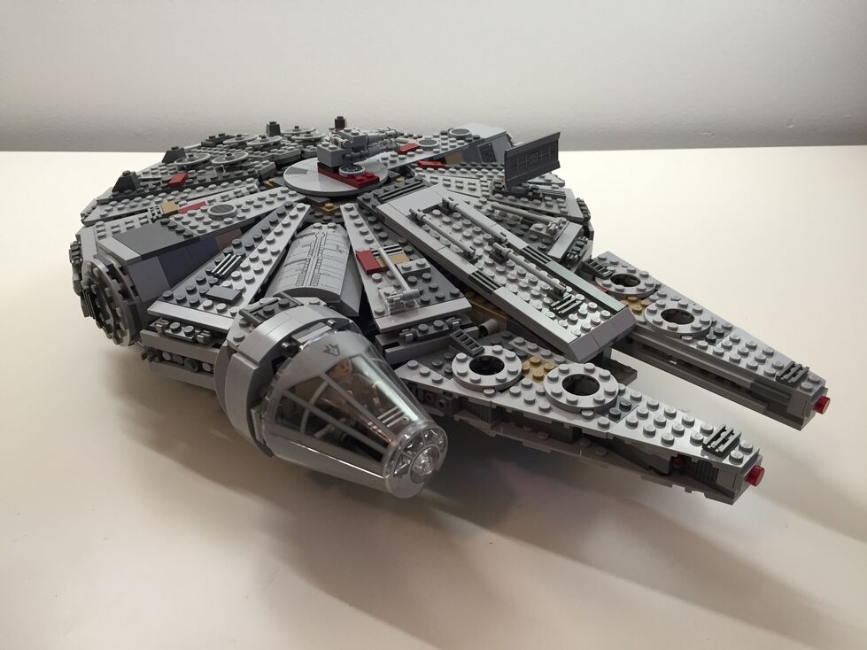
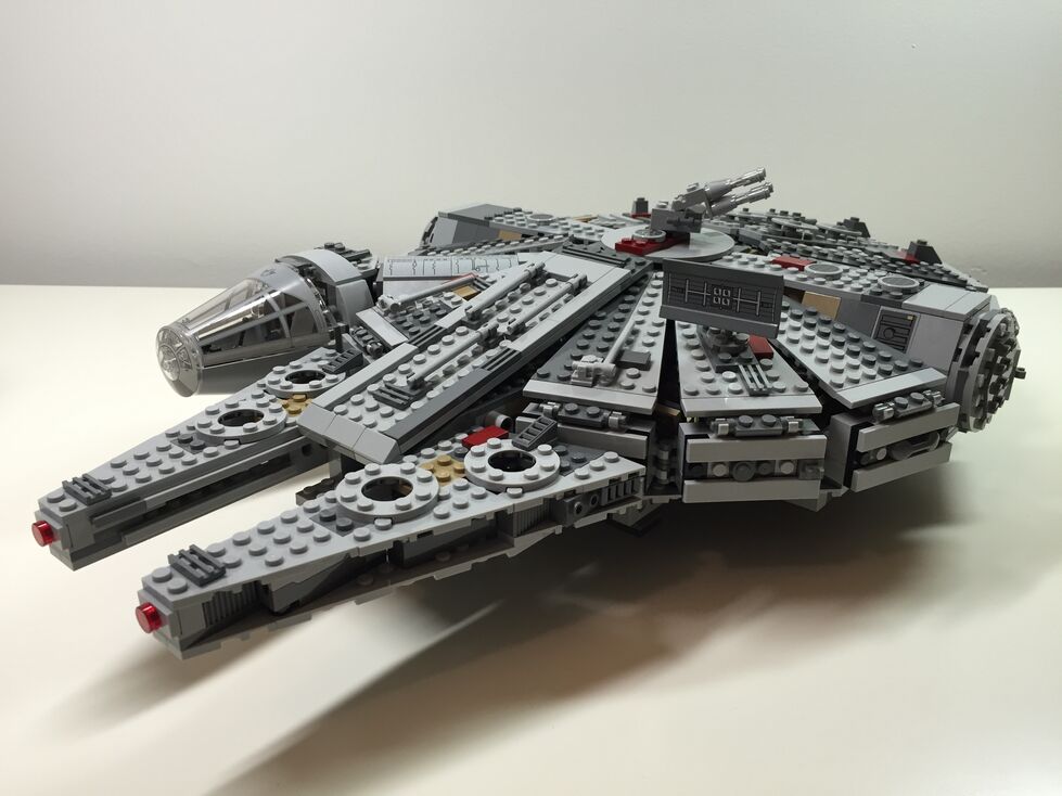
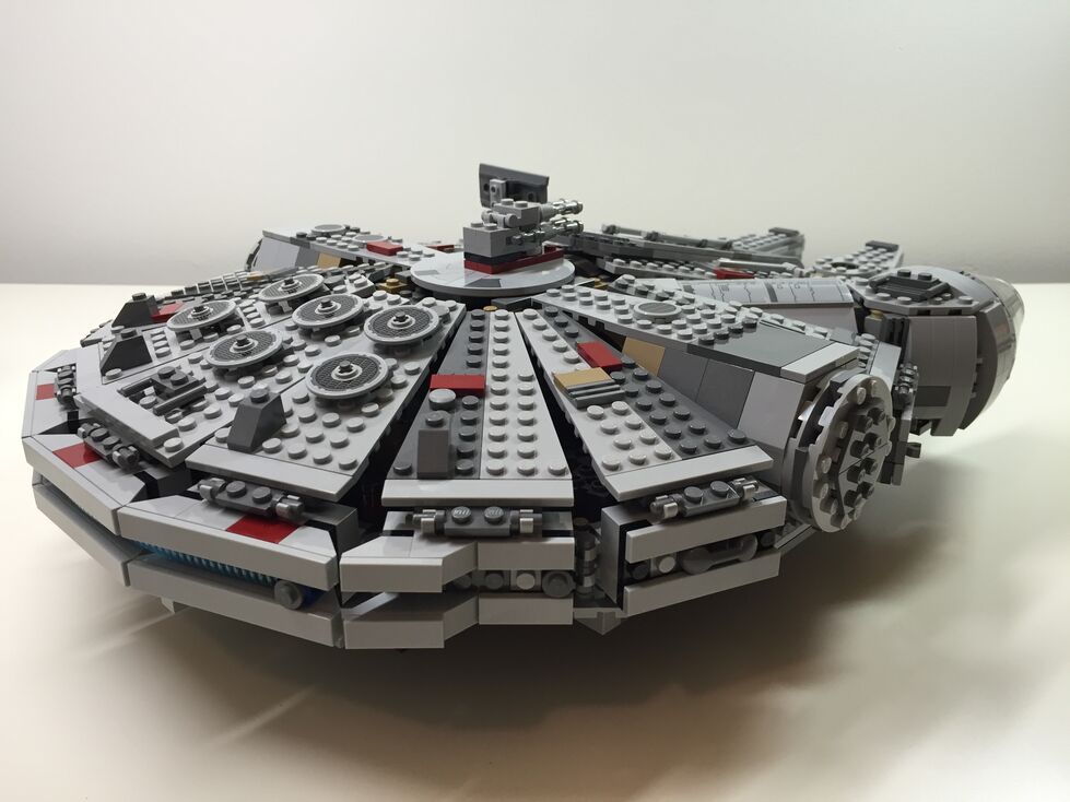
After watching Star Wars Episode VII The Force Awakens for the first of four times (so far), I purchased the new LEGO Millennium Falcon 75105 (LEGO website page and Brickset model page). It is a wonderfully designed model that balances play with detail. This latest Falcon model from LEGO captures how the passage of time and change of hands has affected this storied ship’s appearance in the film. Despite the interior and exterior greebling, the layout of the Falcon is spacious and accommodating for customization by the LEGO builder. It was my intention to customize the Falcon to be more screen accurate in the main hold and cockpit, and more detailed in the engine compartment and rear storage/bunk spaces. Through the process of customization, I worked on the exterior dorsal and ventral sides (including an improvement to the boarding platform. Below, I offer some explanation and photos for each before and after stage of my customization, including the cockpit, exterior dorsal, exterior ventral, interior fore, and interior aft.
Cockpit, Before Customization
The original cockpit accommodates two minifigures–one sitting forward on the right (pilot) and one sitting one row behind on the left (copilot). It comes with a single lever for control and a printed wedge brick with cockpit controls. Due to the conical elements used for the cockpit, space is extremely limited. However, the rear of the cockpit has a strange design that is not evocative of the rear of the cockpit, which would have controls, lights, and a door. I targeted these issues in my customization seen below.
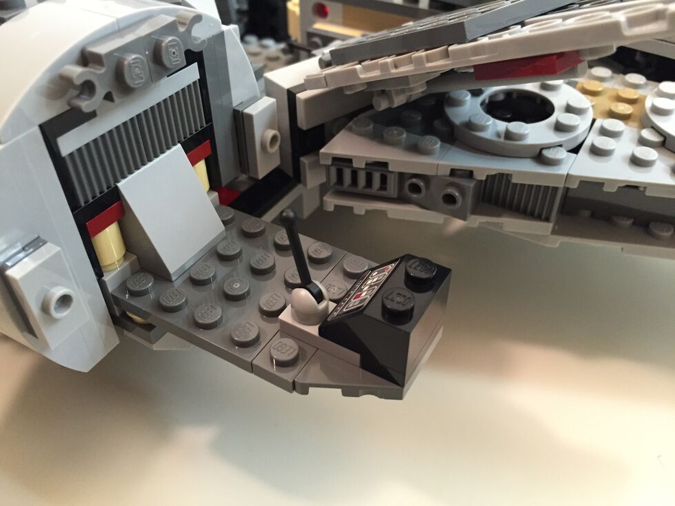
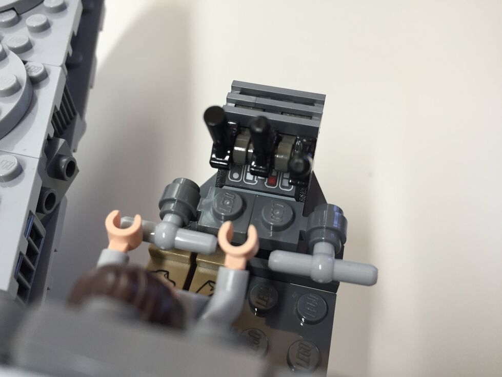
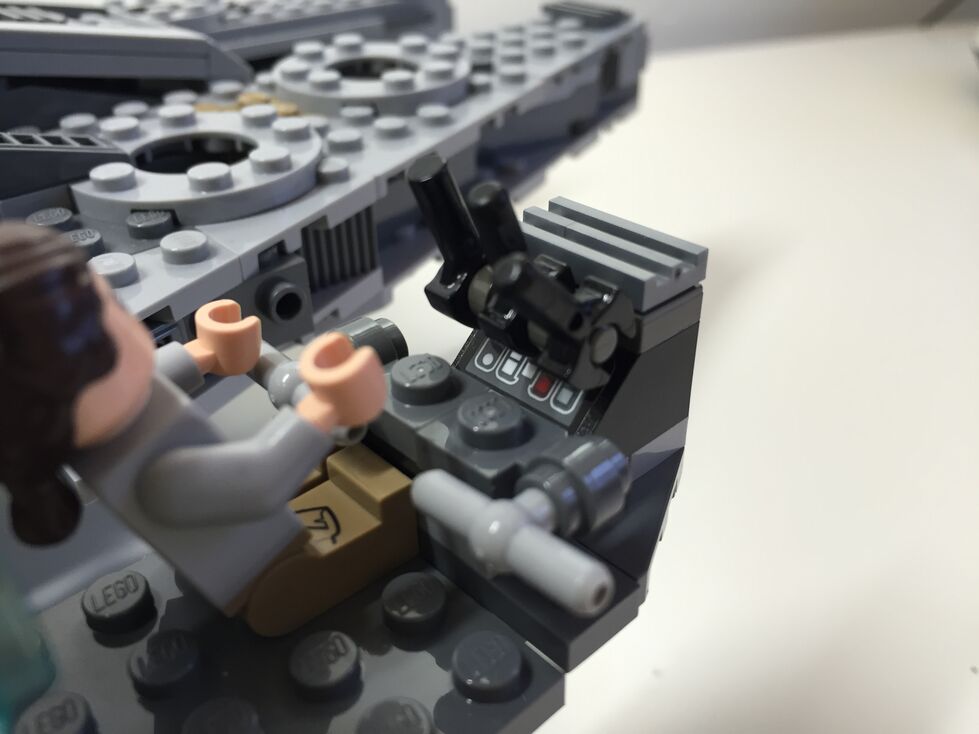
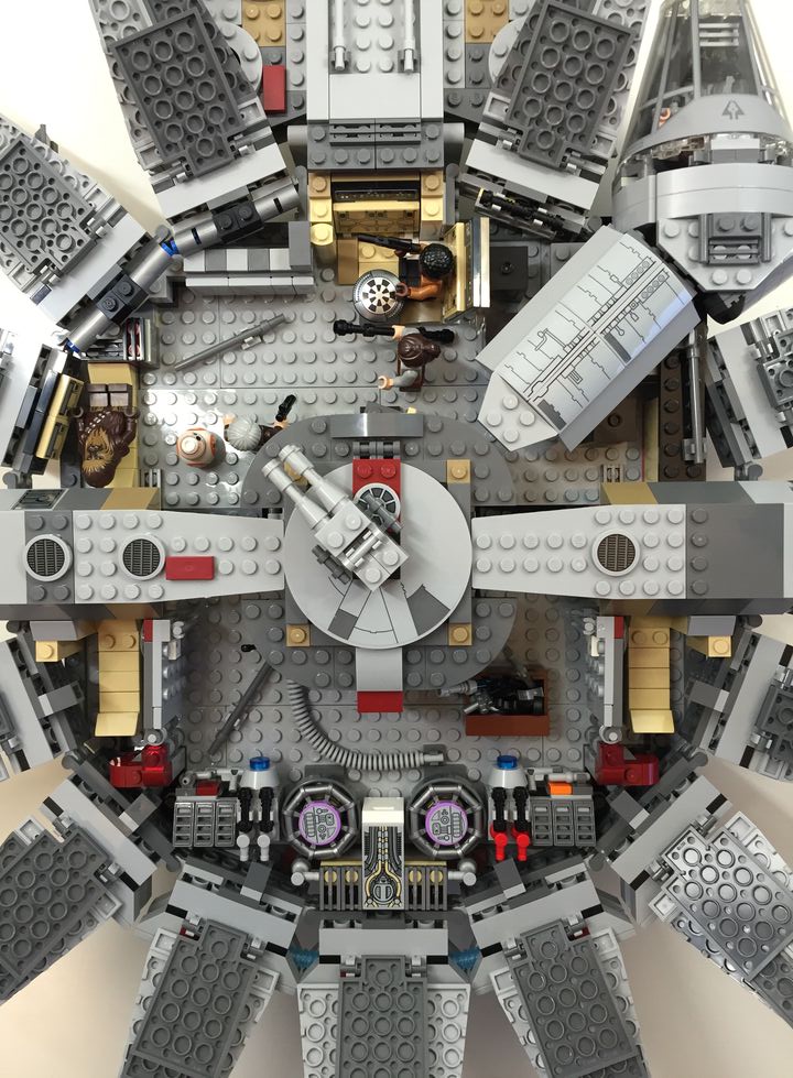
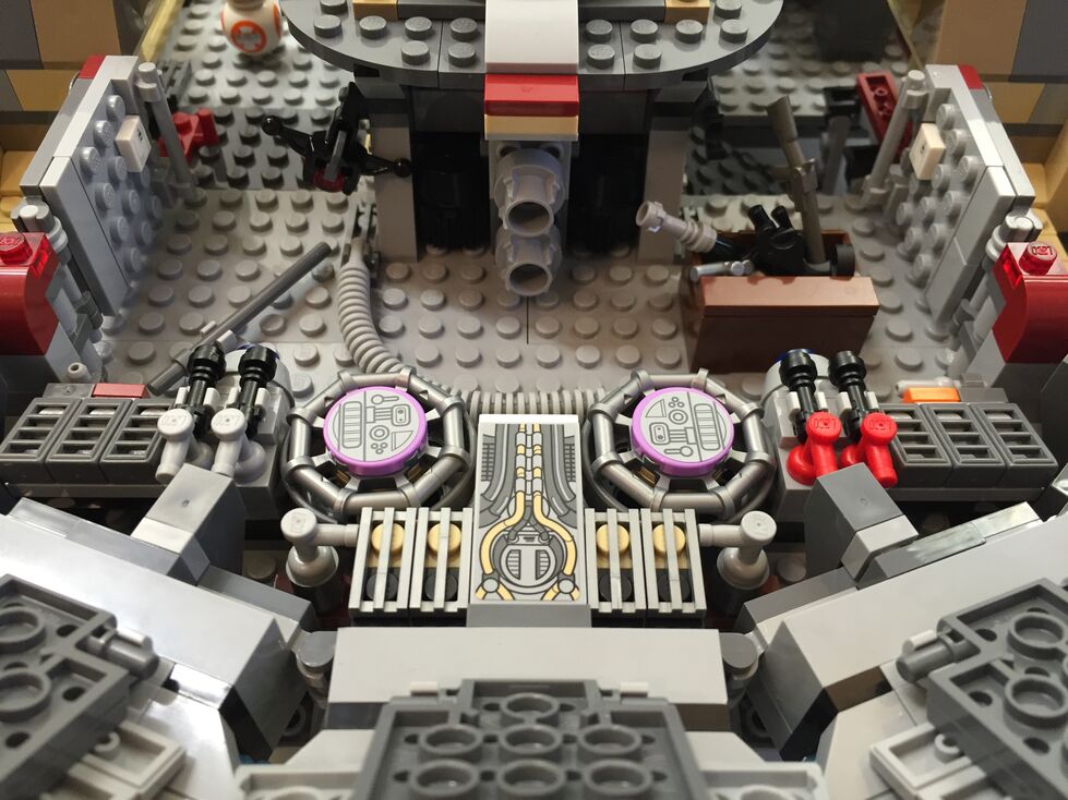
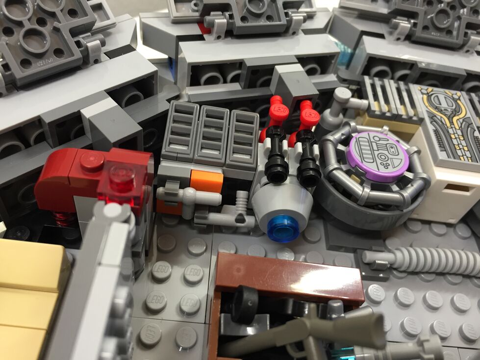
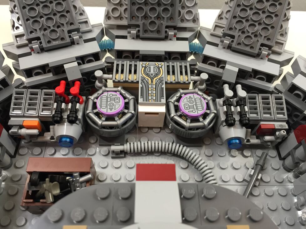
Cockpit, After Customization
In my customization of the cockpit interior, I raised the control panel by one plate and gave the pilot and co-pilot handle-bar controls like in the films. Above the directional control bars, there are three adjustable levels sitting on top of the printed control panel wedge brick for controlling the engines.
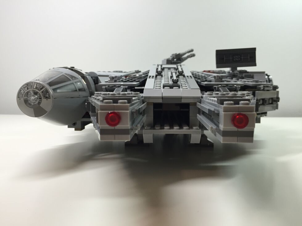
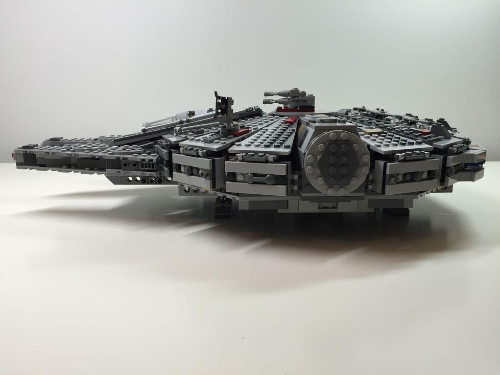
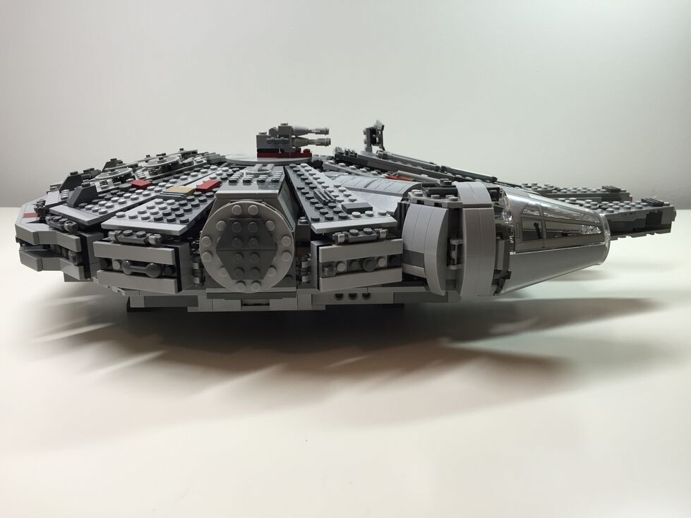
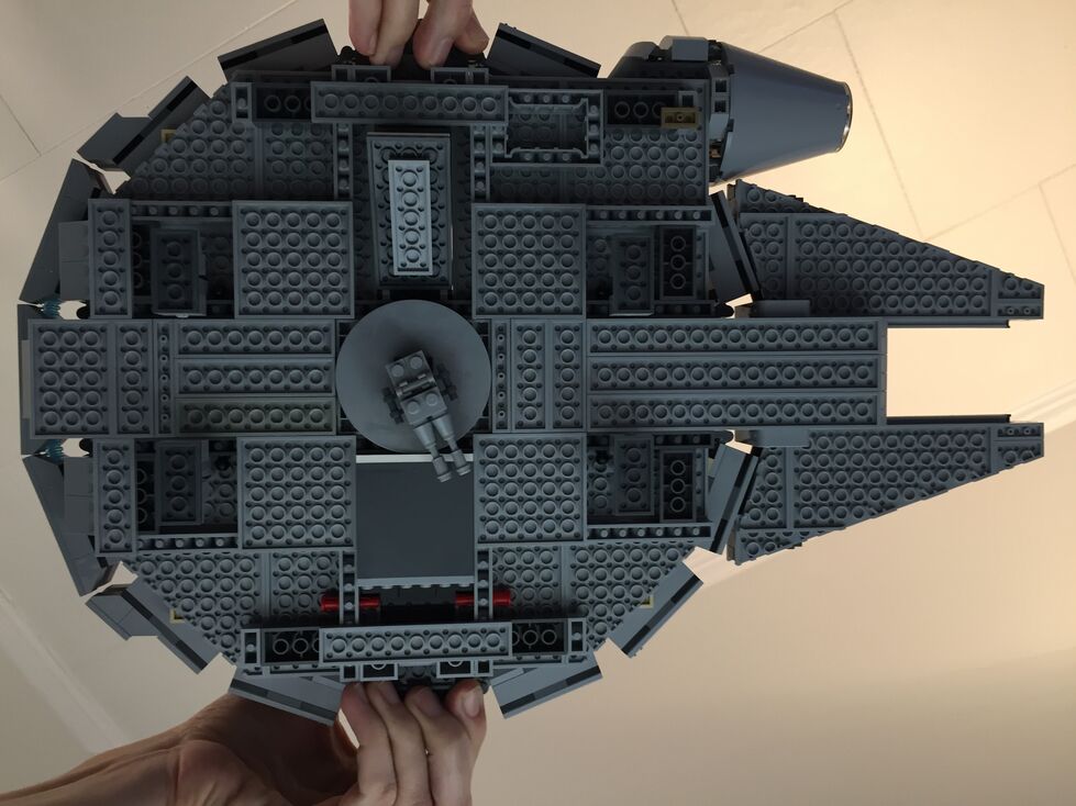
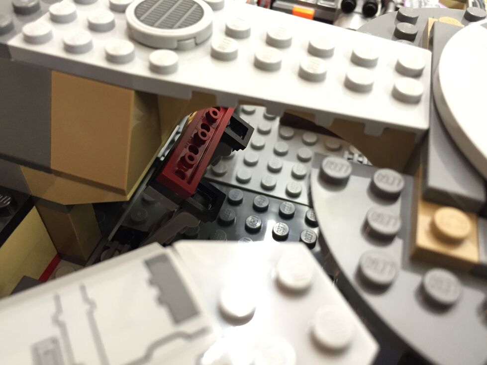
Exterior Dorsal, Before Customization
These images are of the Falcon’s exterior before any customization. Of note, the Millennium Falcon’s fore running lights are red instead of clear (a change depicted in The Force Awakens), and a less clean exterior to illustrate its aging and modifications.
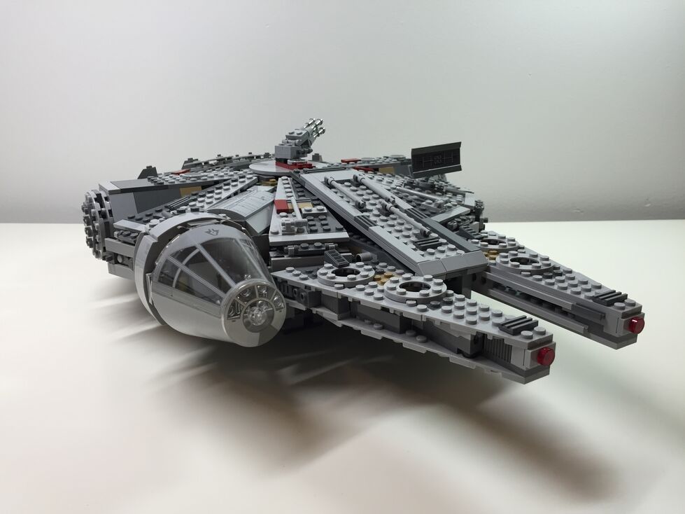
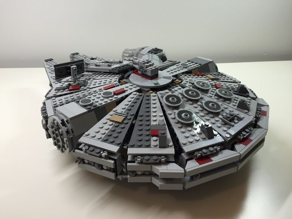
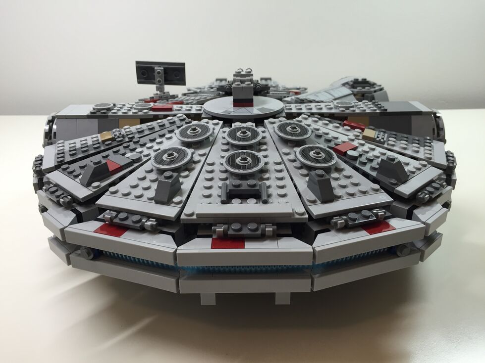
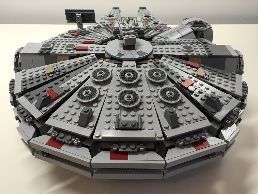
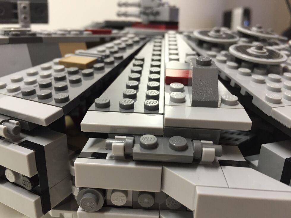
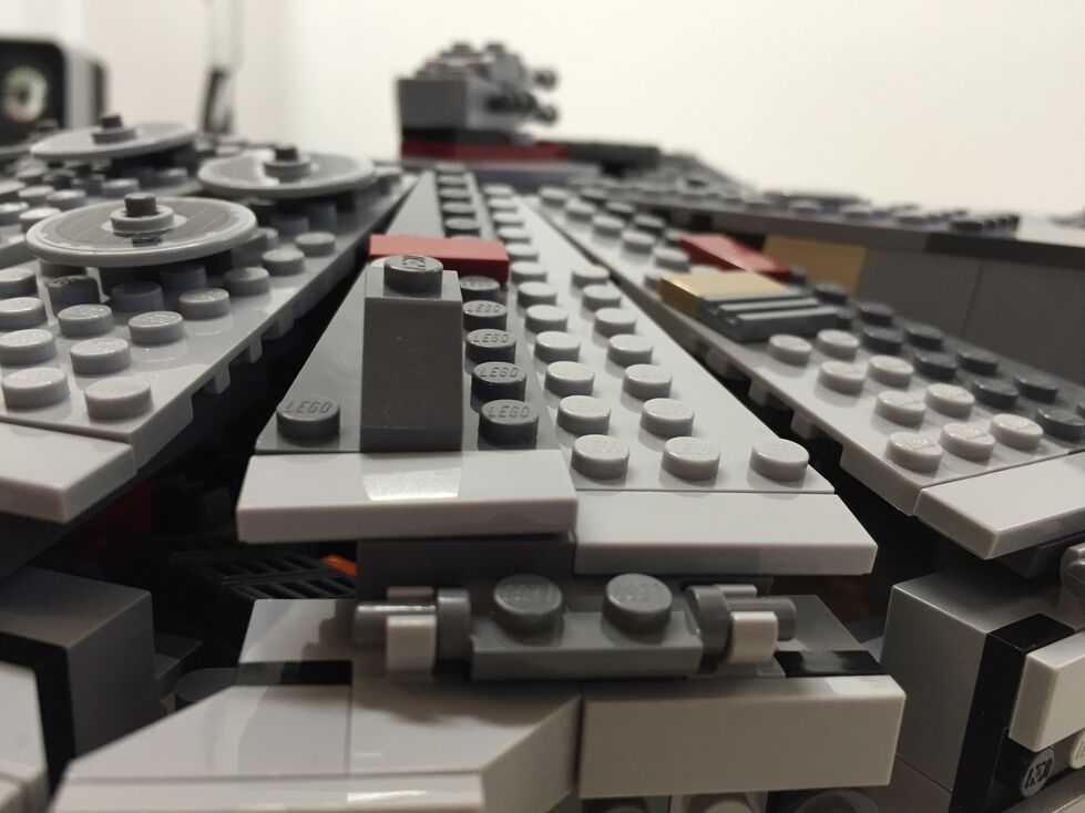
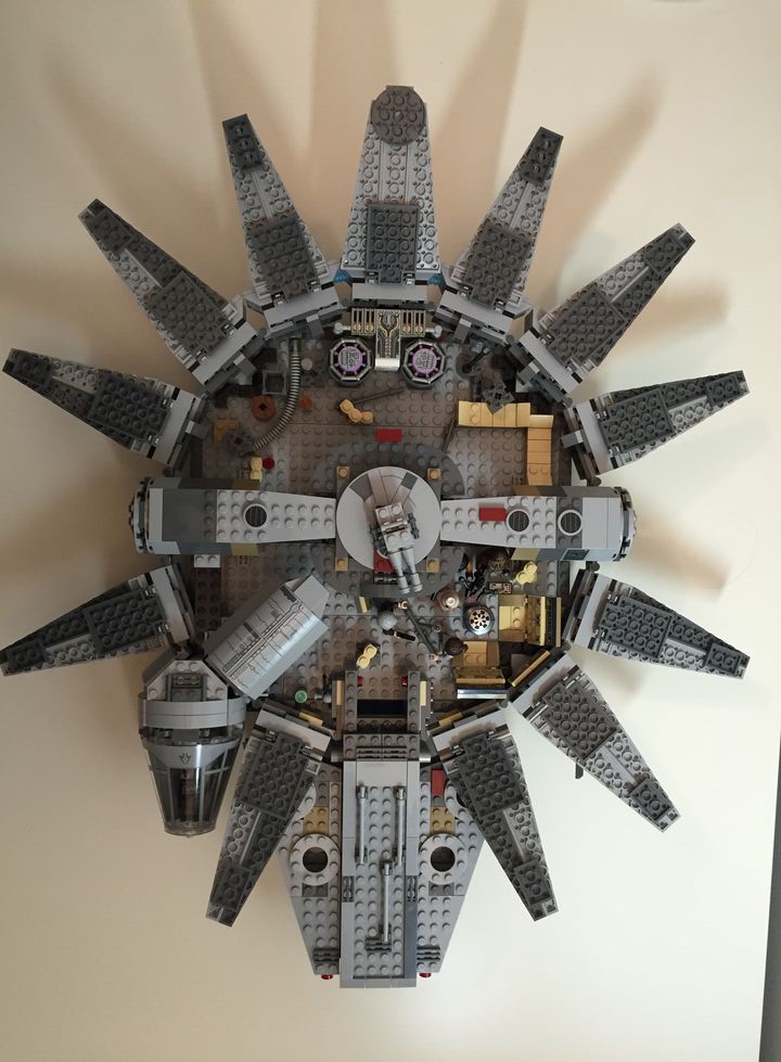
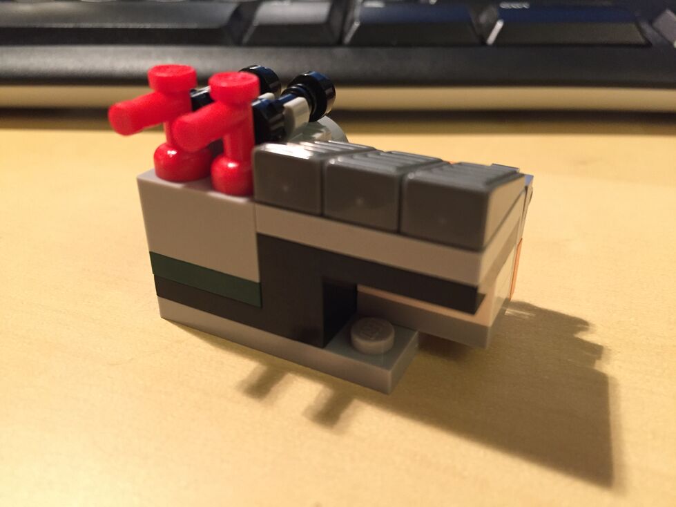
Exterior Dorsal, After Customization
The one external element that I wanted to accentuate as much as possible was the slightly raised panels above the rear quarter over the engines. This was easily accomplished by adding a single plate above the hinge for each sectional panel, and adding a single plate height to half of the bordering panels. The latter, however, also required finding 1×3 flat plates for the segmented panels as seen below.
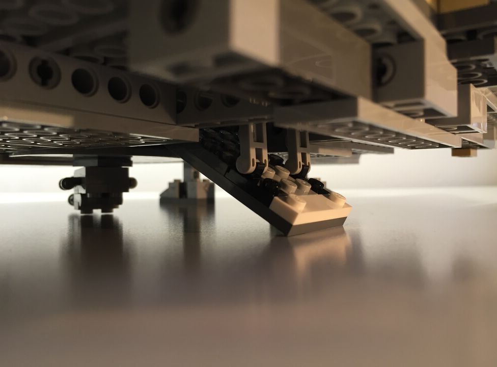
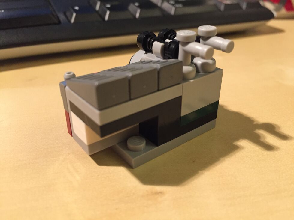
Exterior Ventral, After Customization (no Before photos taken)
Originally, the boarding platform does not have hydraulic lifters and the bottom of the Falcon is largely exposed to the Technic beams that form the support skeleton for the model. I added the lifters and covered much of the bottom (more can be done when I have the bricks available to accomplish a better approximation of the Falcon’s bottom exterior (angled forward pods and rear hold pod beneath the engines).
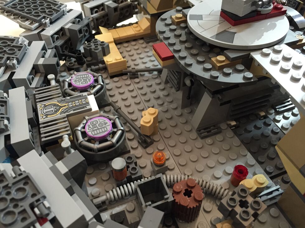
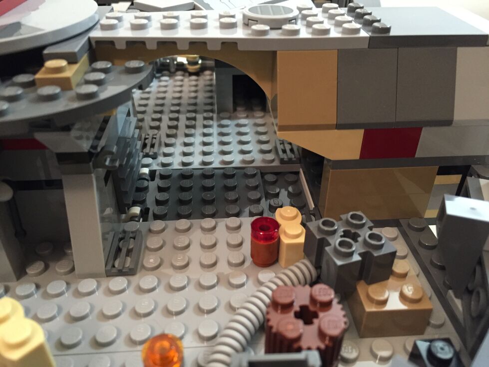
Interior Fore, Before Customization
The 75105 Millennium Falcon model continues the innovative “petal” design forming the dorsal fuselage of the spacecraft, which first appeared in the 4504 set and was improved in the 7965 set. The best change from the earlier designs is for the forward bisecting panel leading from the mandibles to the gun turret. Instead of opening up toward the turret (4504) or opening forward toward the mandibles (7965), the panel now swings forward and down between the mandibles thus giving easier access to the builder for play inside the Falcon. The navigational computer is more accurately captured with a sticker applied to a flat plate than printed wedge bricks in 7965, and the Dejarik table is printed on a round shield element. My complaints with the interior design have to do with the inaccuracy of the placement of the Dejarik table/benches and bunks. I focused on this in my customization.
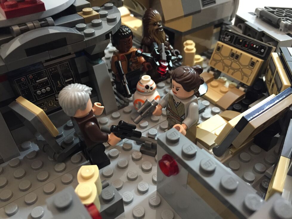
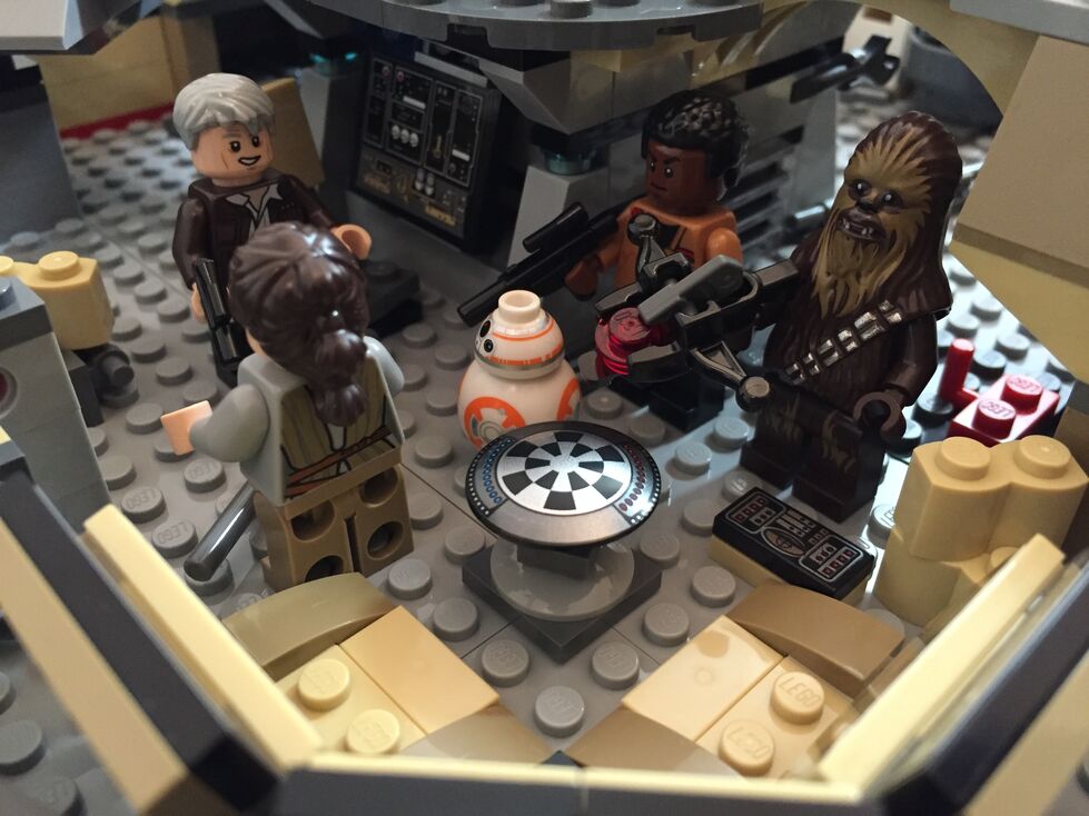
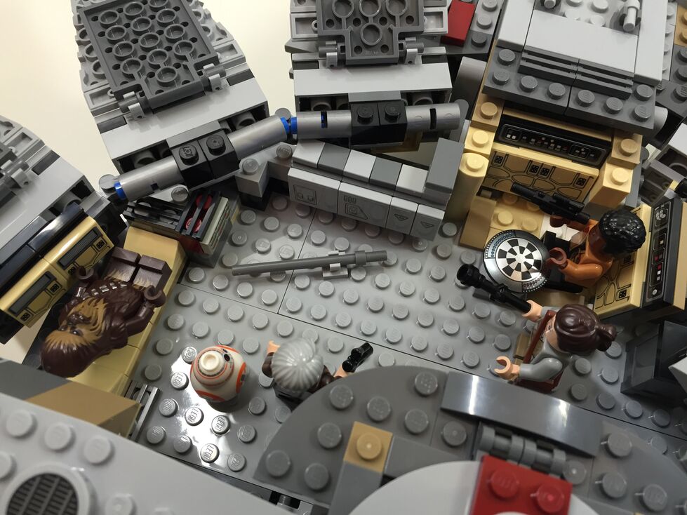
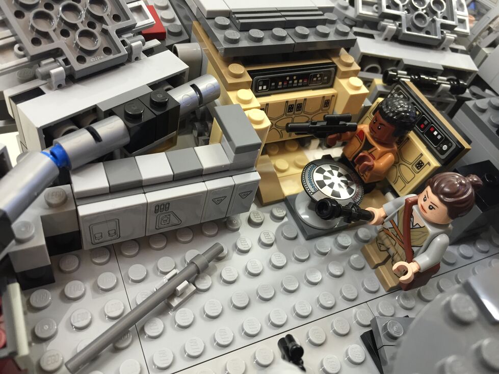
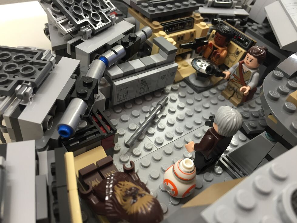
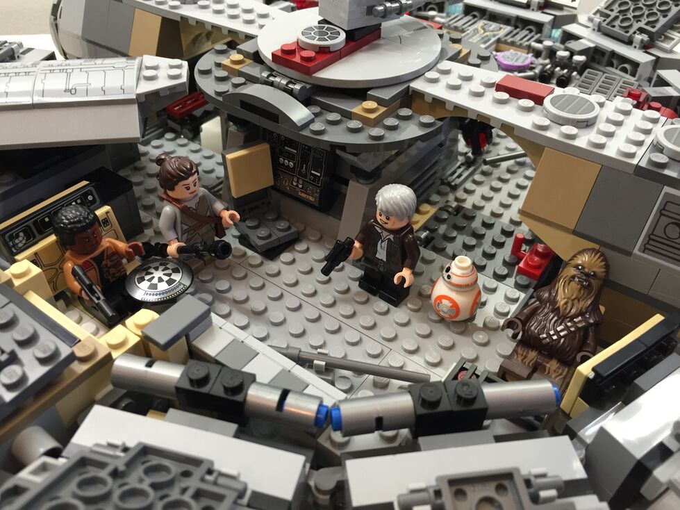
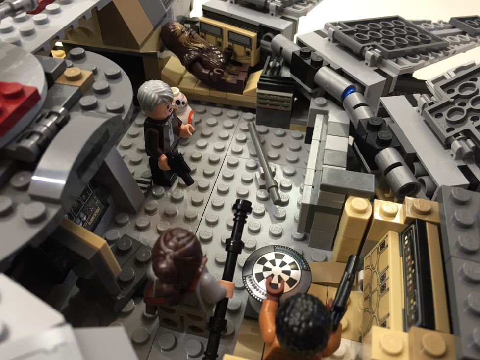
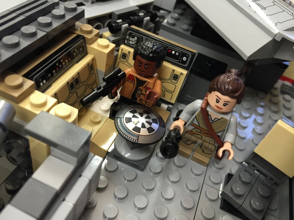
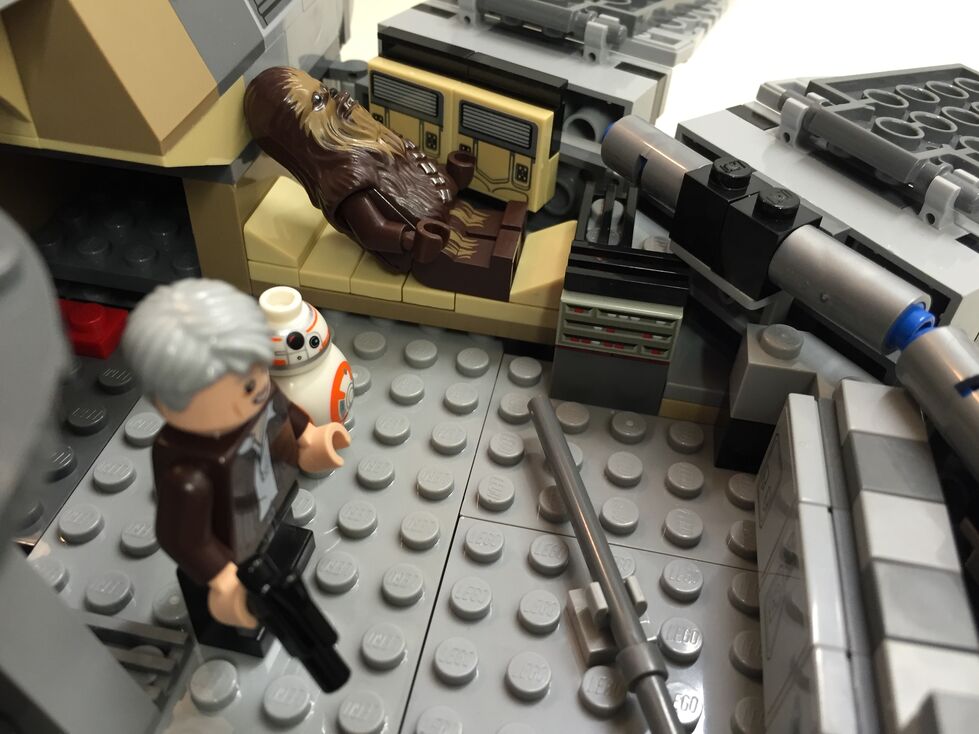
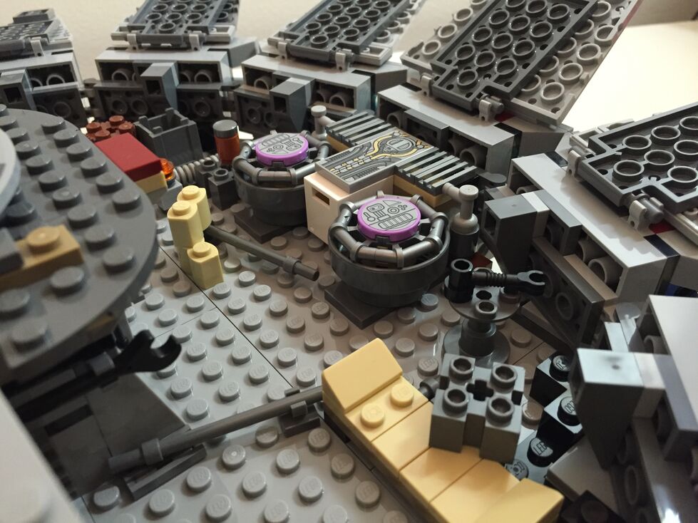
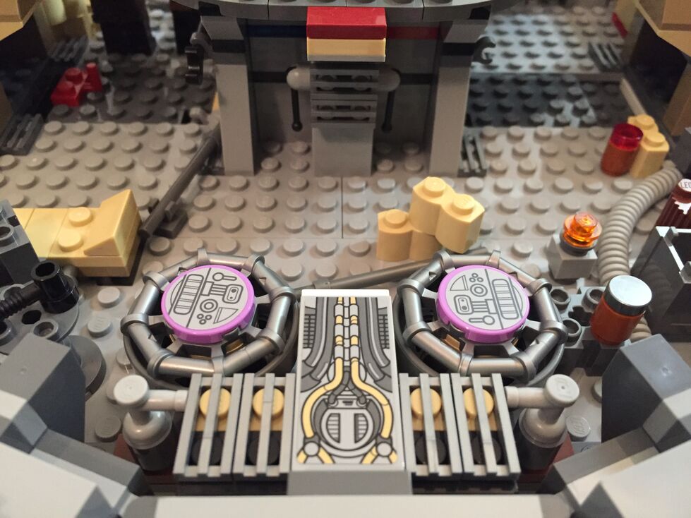
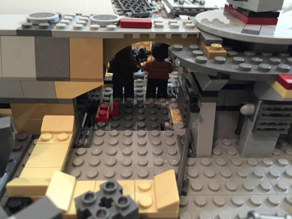
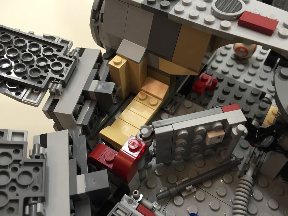
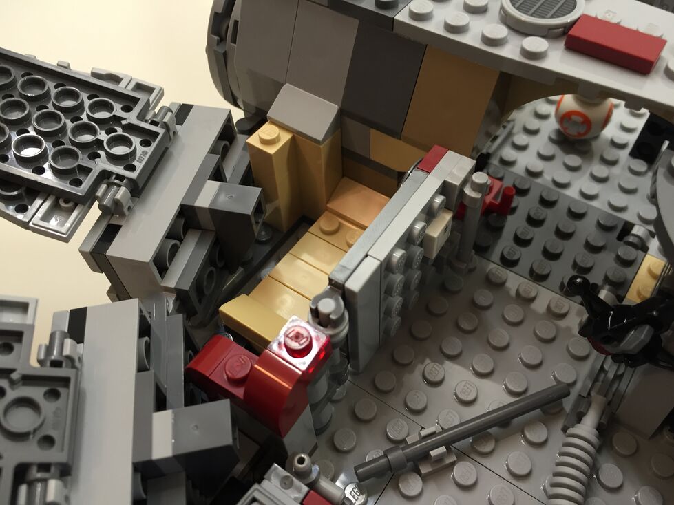
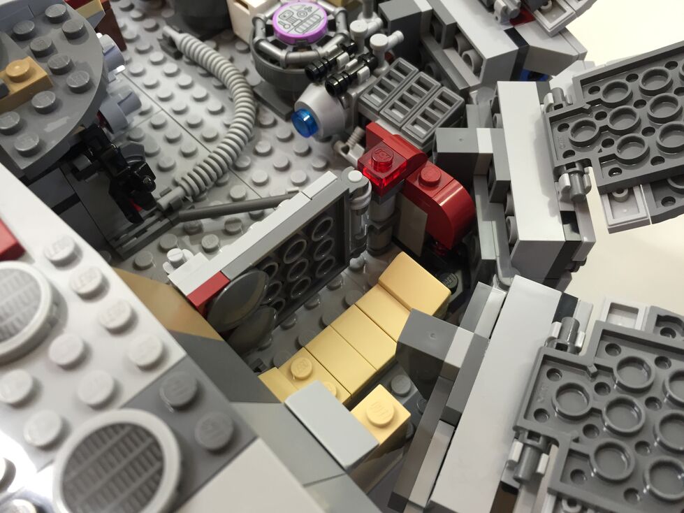
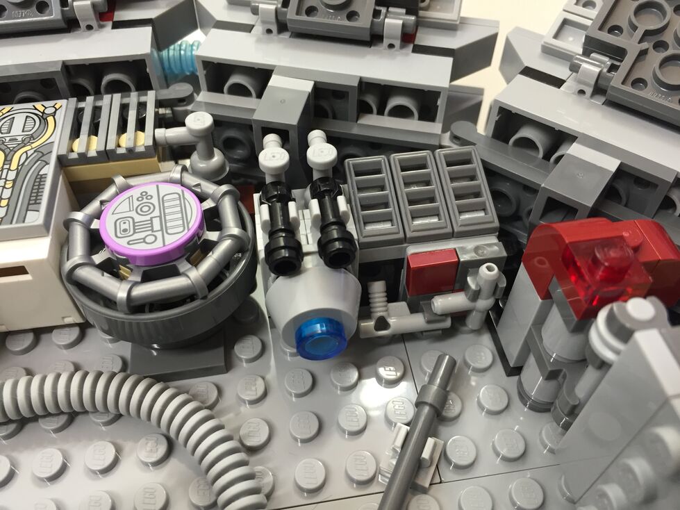
Interior Fore, After Customization
In my customization, I moved the Dejarik table and benches across from the navigation computer, which required rebuilding part of the mandible supports and the swing components for the center panel (to clear the center bench back). I relocated one of the bunks to the end of the hold to create the medibay where Finn bandages Chewbacca’s arm. In the main hold, I constructed a forward wall with panel details taken from the First Order Snowspeeder 75100 set.
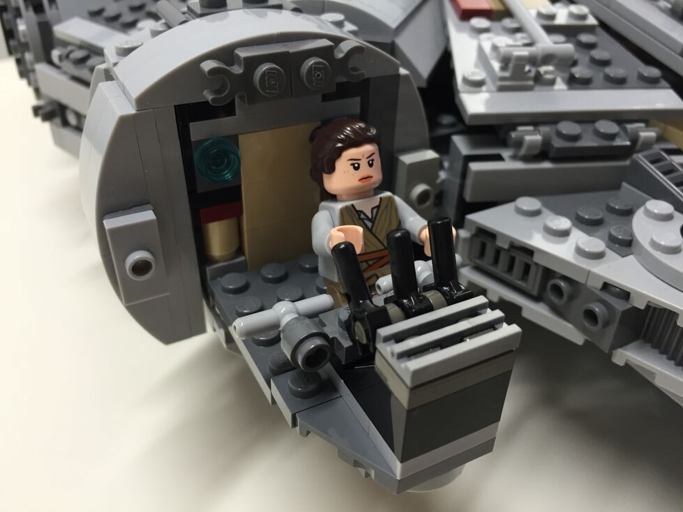
Interior Aft, Before Customization
The engine compartment in the rear of the model is similar to the one in 7965. This part of the Falcon captures the junked essence of the Falcon in general and the effects of the passage of time and unkind handling of the Falcon depicted in The Force Awakens. I wanted to keep its garbage appearance while giving the engine compartment greater substantiality.
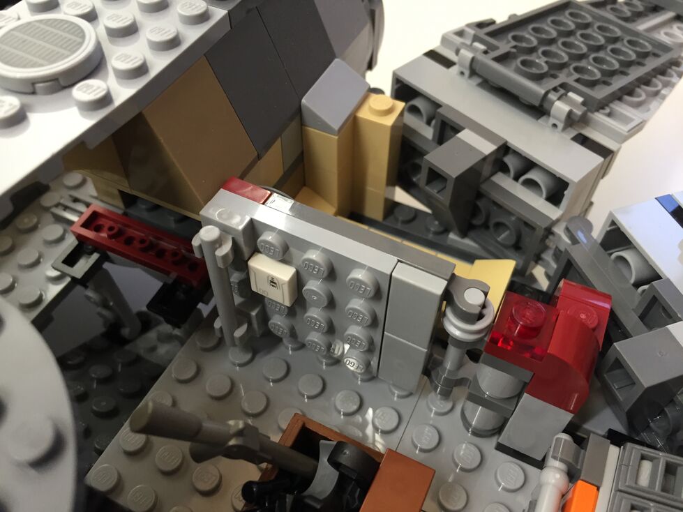
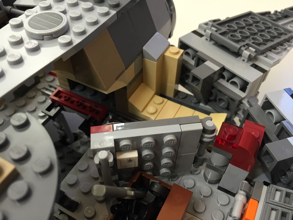
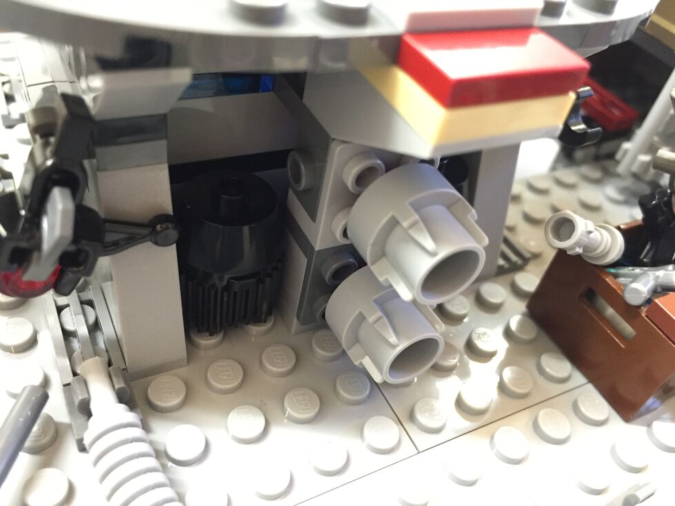
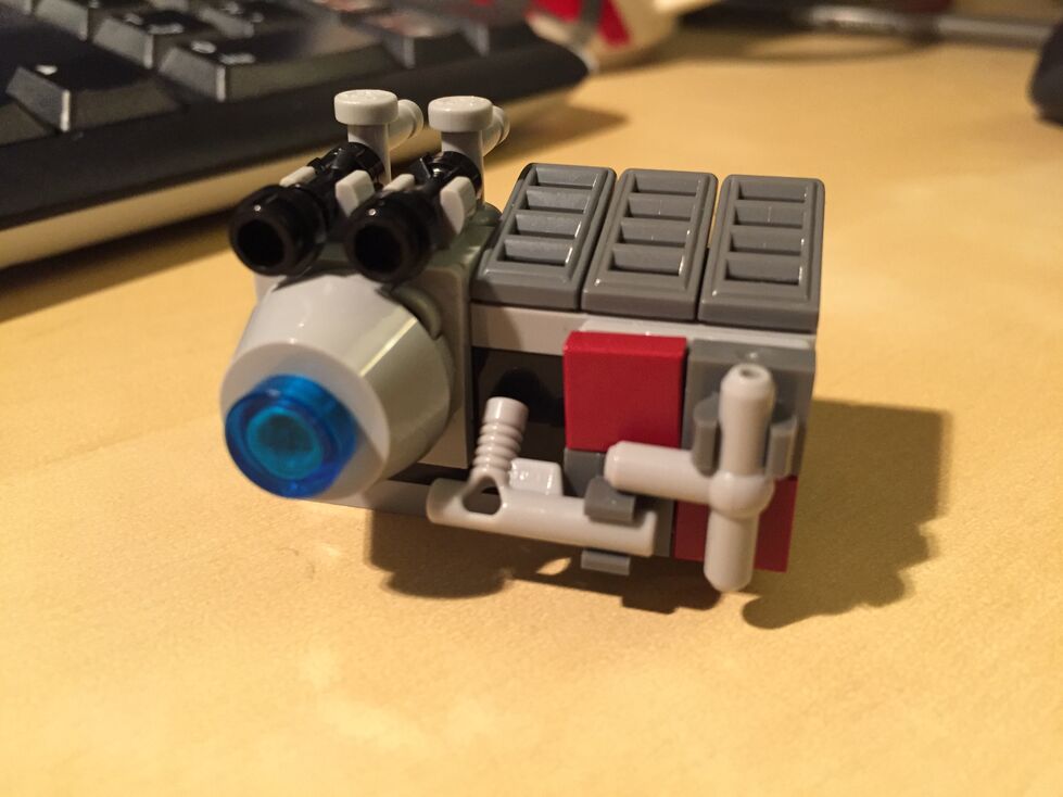
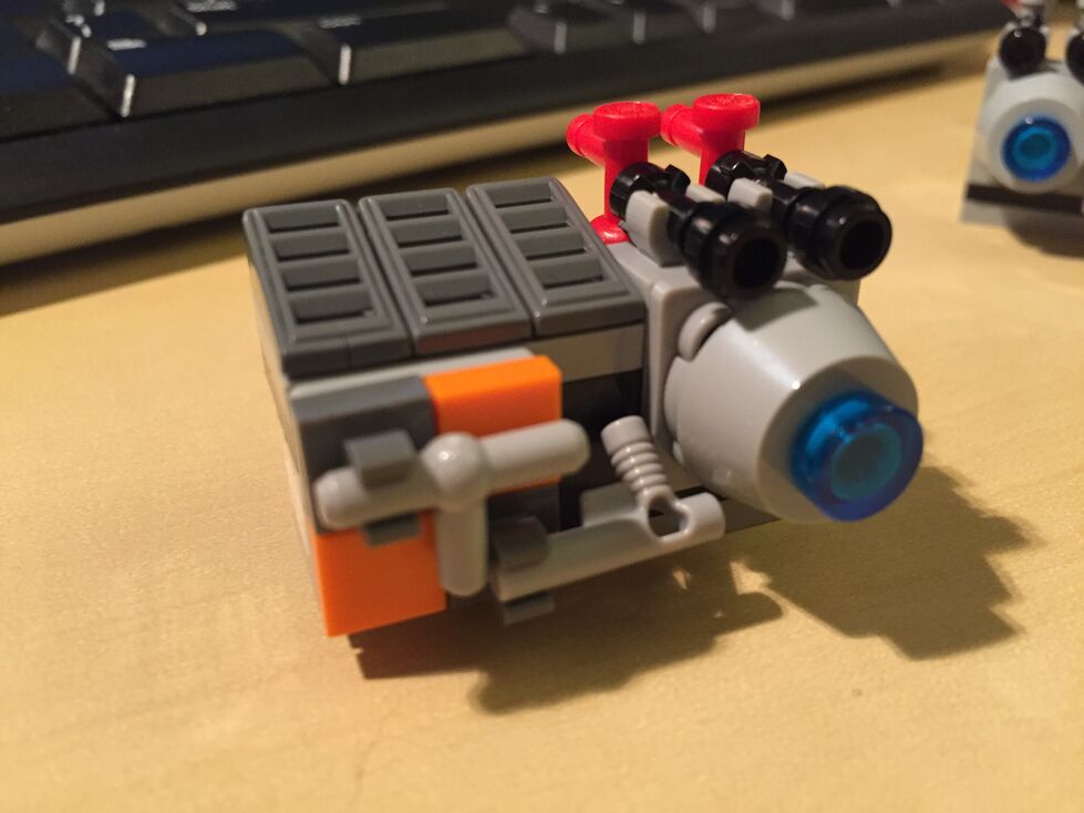
Interior Aft, After Customization
In the rear hold/engine compartment, I constructed two storage rooms/bunks with swinging doors (I would have preferred to have sliding doors but I don’t have the elements to do this while conserving the limited space available), and I designed additional mirrored engine modules that go on either end of the original engine included with the set, which I hope makes the engine look more substantial for a spacecraft capable of completing the Kessel Run in 14, er, 12 parsecs!
Conclusion
I hope to further customize the 75105 Millennium Falcon. As I acquire new bricks and elements, I would like to think about how to better integrate the engines into the design and aesthetic of the YT transport. Other goals include, integrate a mechanism for lowering and raising the boarding platform, similar to the 4504 set, design screen accurate landing gear that raise the Falcon by at least one plate higher while on display, and further integrate my customization into the model so that it attains a unity of design instead of a piecemeal added-on quality.
If you have customized the 75105 or other Millennium Falcon sets, please sound off in the comments. Thanks for stopping by!
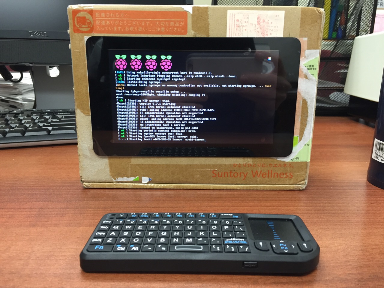
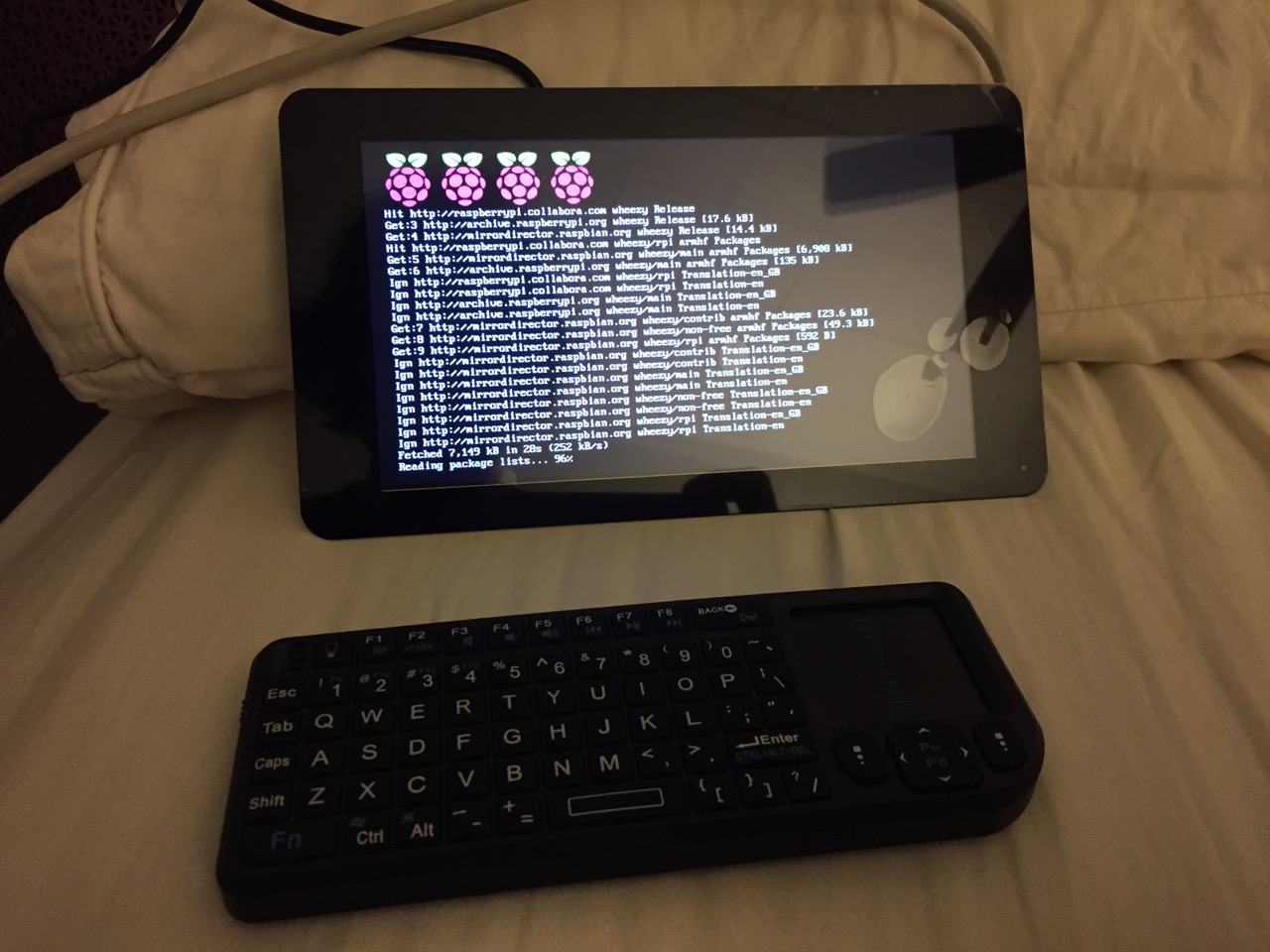
My Cardboard Box Raspberry Pi 2, Model B with 7″ Touchscreen Display and wireless keyboard.
This guide demonstrates how to install Raspbian on a Raspberry Pi 2, Model B, connect the Raspberry Pi to a 7″ Touchscreen LCD, and integrate the computer and touchscreen in a cardboard box (which doubles as a case and storage for battery, keyboard, and cables).
I got interested in the Raspberry Pi, because it has many capabilities for learning: kitting out a computer, installing a Linux-based operating system, programming interactive software, and building with electronics. In particular, I am interested in how the Raspberry Pi can be used to create interactive software and be a platform for digital storytelling (which figures into one of the upcoming classes that I will be teaching at City Tech–ENG 3760 Digital Storytelling).
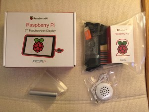
My haul from Tinkersphere.
Instead of buying my kit online, I wanted to shop local to get started. Originally, I considered going to Microcenter, which is near where I live in Brooklyn. Unfortunately, they were sold out of the touchscreen display that I wanted. Instead, Y and I took a train into Manhattan and visited Tinkersphere where one of their helpful staff guided me to the things on my digital grocery list. I purchased Tinkersphere’s pre-made Raspberry Pi 2 kit, a 7″ Touchscreen LCD display, a battery pack (in retrospect, I should have purchased two of these, which I will discuss below), and a mono speaker with 1/8″ plug.
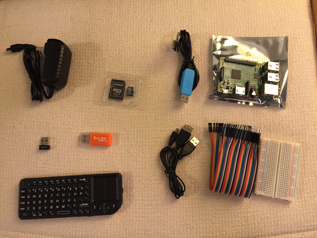
Contents of Tinkersphere’s Raspberry Pi 2, Model B kit.
Tinkersphere’s Raspberry Pi 2, Model B kit includes all of the basic equipment needed to begin working with this tiny computing platform. The kit is built around the Raspberry Pi 2, Model B computer with a 900MHz quad-core ARM Cortex-A7 CPU, 1GB RAM, 4 USB ports, 40 GPIO pins, HDMI port, ethernet port, combined 3.5mm audio jack and composite video, camera interface (CSI), display interface (DSI), micro SD card slot, and a VideoCore IV 3D graphics core. Additionally, the kit includes a wireless keyboard/trackpad, USB wifi adapter, 8GB micro SD card with NOOBS (the easy to use Raspbian installer), USB micro SD card reader, breadboard, wires, and 5v power supply.
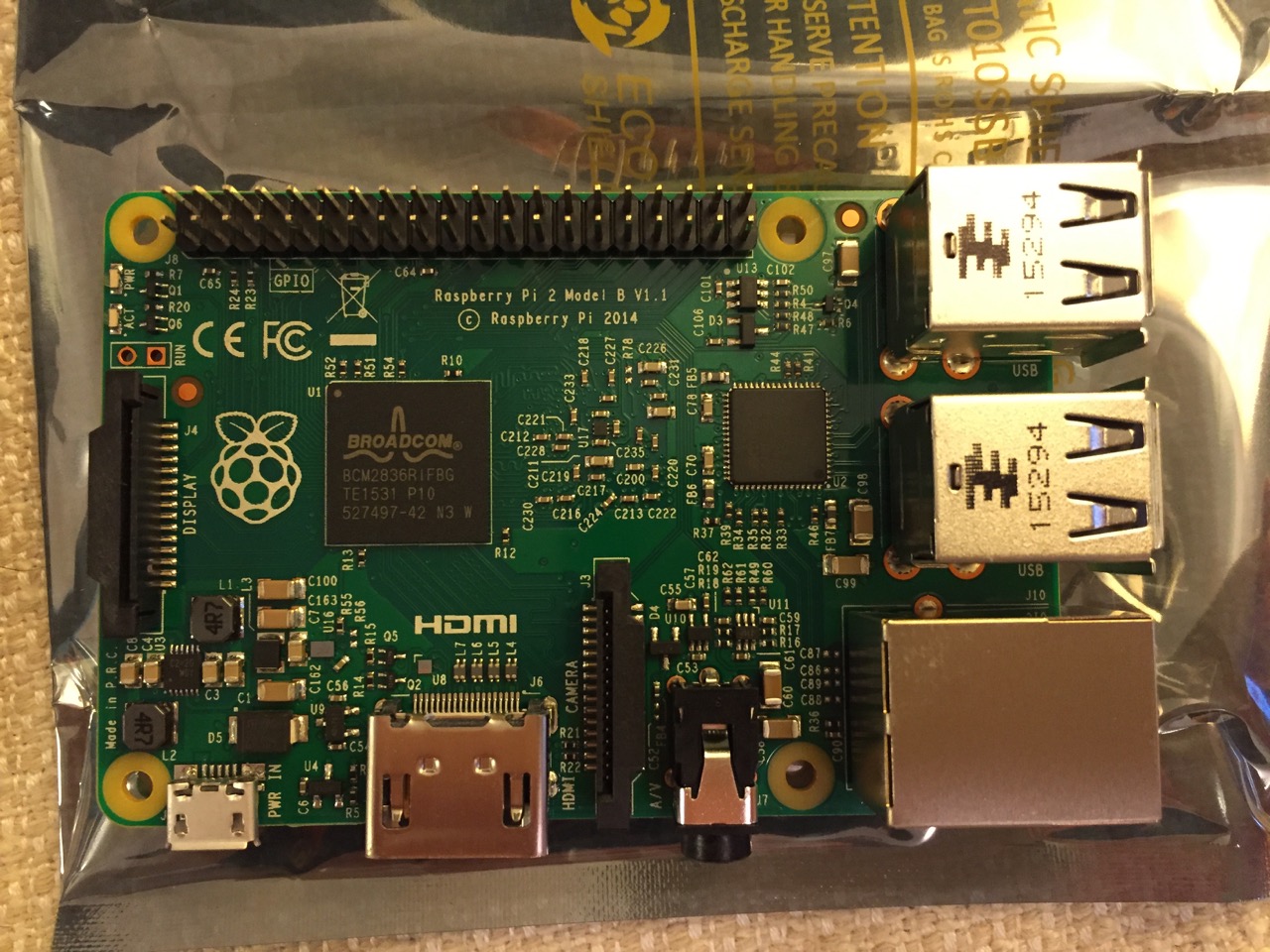
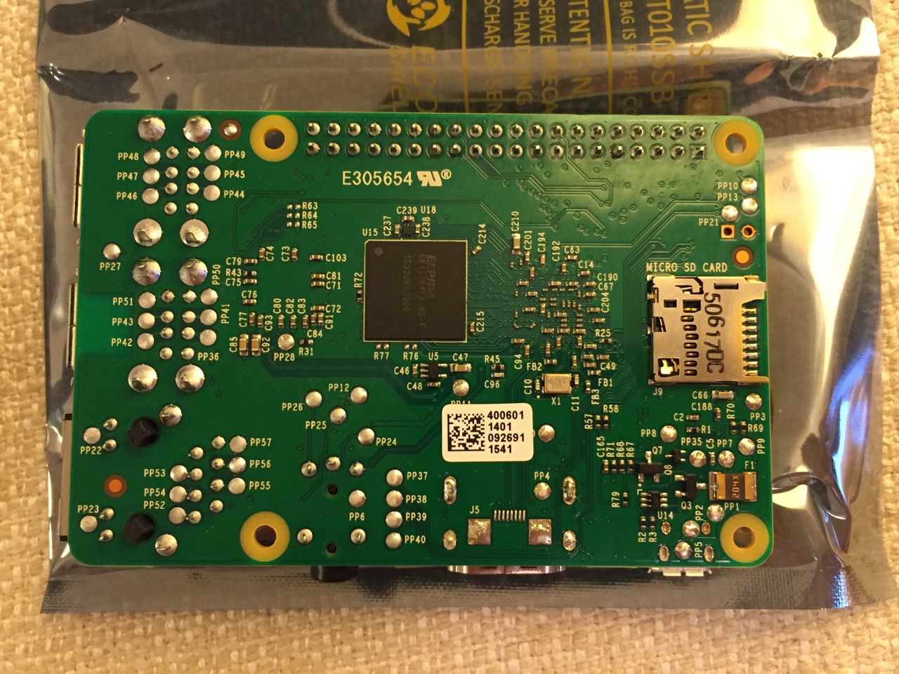
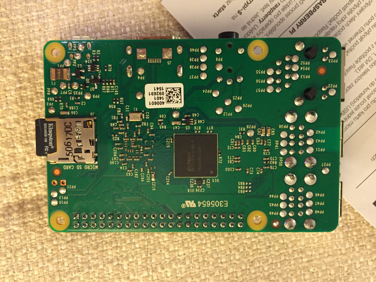
To begin the setup, we should orient ourselves with the Raspberry Pi. This is the Raspberry Pi 2, Model B computer viewed from the top and the bottom:
Raspberry Pi 2, Model B, Top View.
Raspberry Pi 2, Model B, Bottom View.
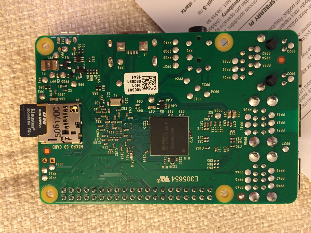
The first thing that we need to do is insert the micro SD card with a copy of NOOBS pre-copied. If you need a copy of NOOBS for your own micro SD card, you can download it from here and follow the instructions here for formatting and copying the files from a Mac or PC to the micro SD card. The Raspberry Pi’s micro SD card slot is located on the bottom side of its circuit board. A micro SD card goes in only one way which allows you to press it in. If correct, the card should “click” and stay as seen in the photos below.
Insert the micro SD card like this.
Press the micro SD card in and it will stay in place with a “click.”
The Raspberry Pi connected from left to right: micro USB power input from 5v power supply, HDMI, wireless keyboard/trackpad receiver, and wifi adapter.
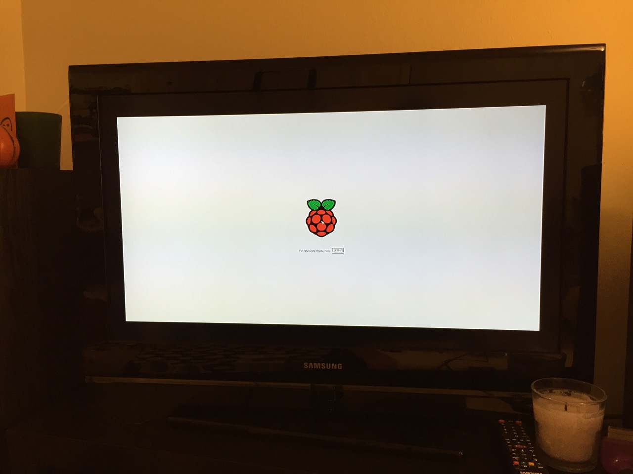
Next, connect the Raspberry Pi to a display (such as a TV) with HDMI, and plug in the wifi adapter and wireless keyboard into two available USB ports. Alternatively, you can connect the Raspberry Pi to the Internet via ethernet and to a wired keyboard and mouse. Then, connect it to the 5v power supply. As soon as it is plugged in, the Raspberry Pi is turned on and operational. It will begin to boot from the micro SD card’s NOOBS installer, which will guide you through the process of installing Raspbian. See the images below to see what this looks like and what choices you should make for a basic installation.
NB: While we could have connected the 7″ Touchscreen Display to the Raspberry Pi before beginning the installation, the current version of NOOBS would not detect and use the touchscreen display. It is necessary for Raspbian to be installed and updated before the 7″ Touchscreen Display will be recognized and used as the Raspberry Pi 2’s primary display.
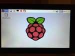
NOOBS boot screen with the Raspberry Pi logo.
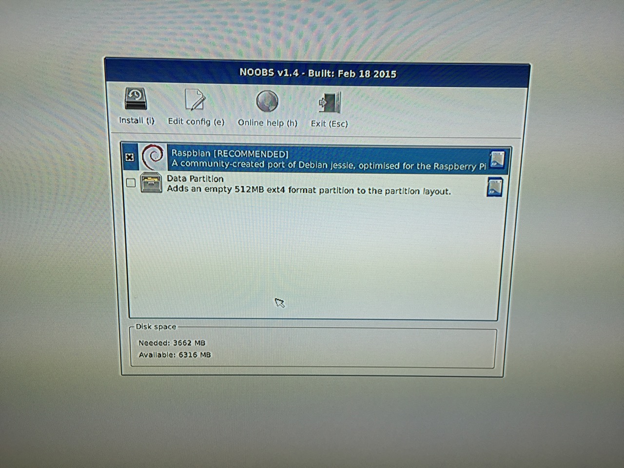
The NOOBS installer asks what you would like installed. Place a check next to Raspbian.
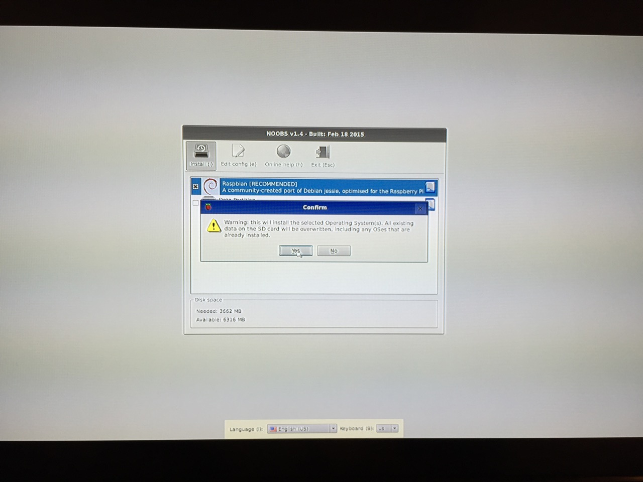
The NOOBS installer will ask that you confirm your choice. If you haven’t already done so, choose US keyboard and locationalization at the bottom of the screen before proceeding. Then, confirm.
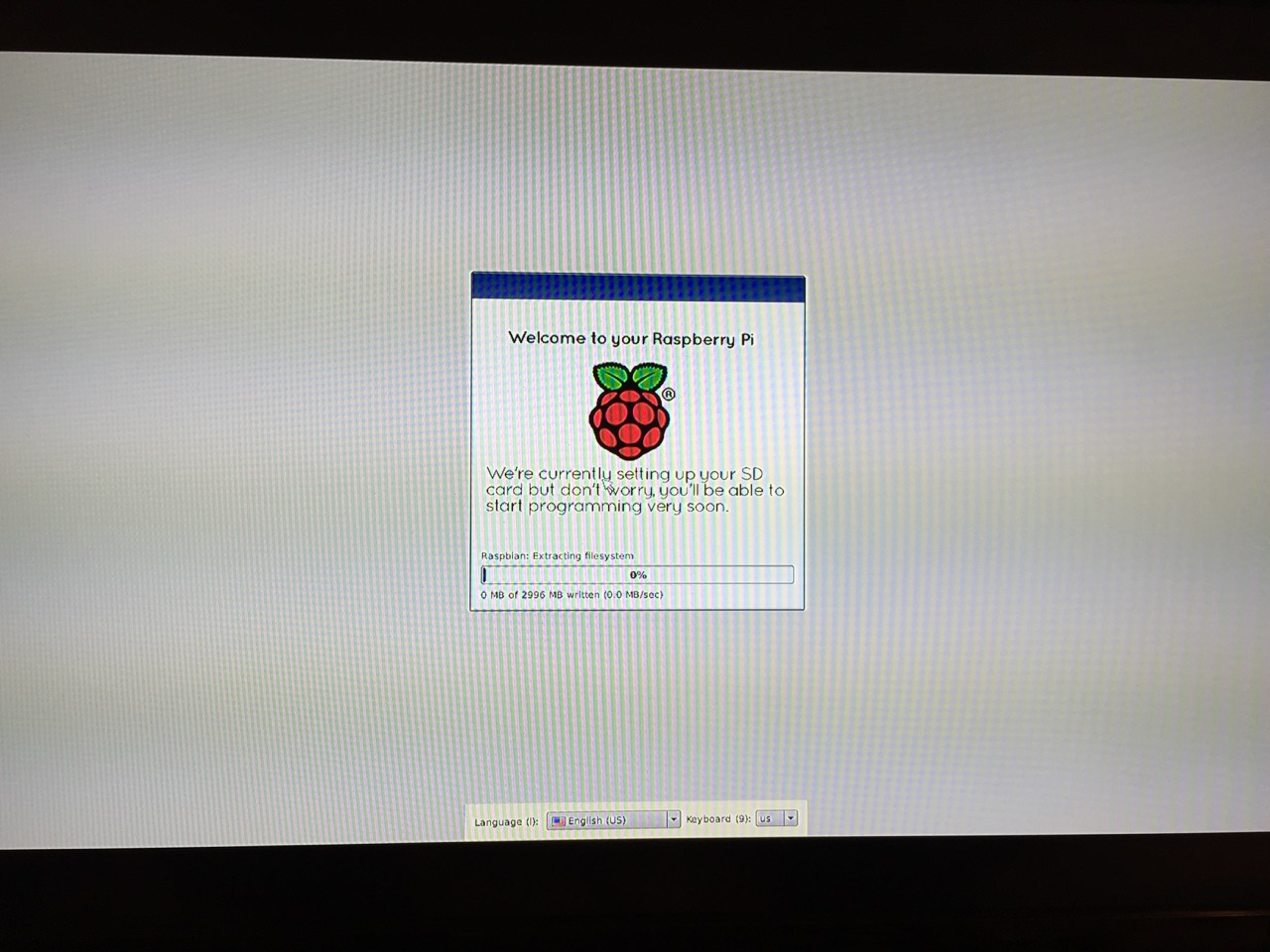
The installation will proceed and complete. With the micro SD card that I have and without overclocking the Raspberry Pi, it took about 20-30 minutes for the installation to complete.
After rebooting following the installation, the raspi-config tool launches. This program gives the user easy access to many configuration options for the Raspberry Pi including how it should boot (automatically login and load xwindows, or boot to a command prompt login), and if you would like to overclock the Raspberry Pi for additional performance (use this option with caution–you will likely want to add heat sinks and increased ventilation if you overclock the system). I configured my Raspberry Pi to operate at normal speed and to boot to the command line with login.
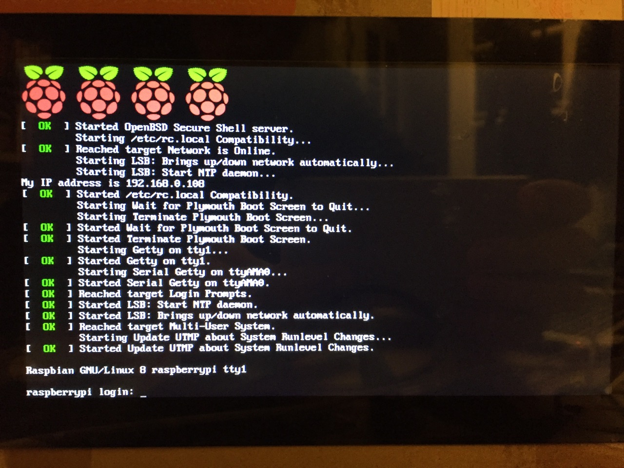
After booting into Raspbian, the first thing that you see is the login prompt.
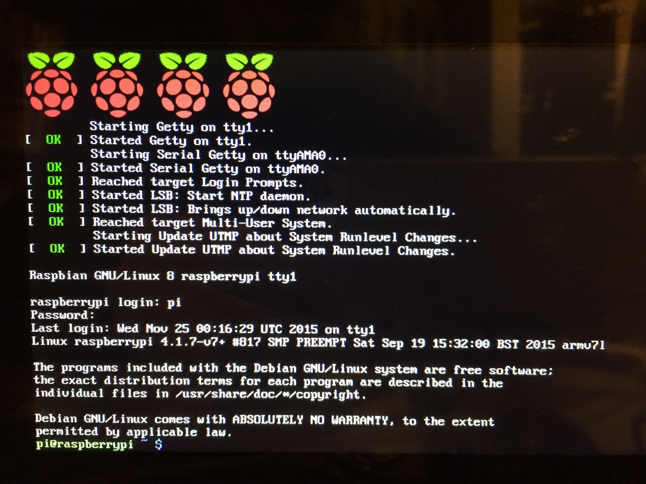
The default login for the Raspberry Pi is username “pi” and password “raspberry”. Type each of these credentials in when asked followed by pressing the Enter key. Then, you will find yourself at the command line interface (CLI).
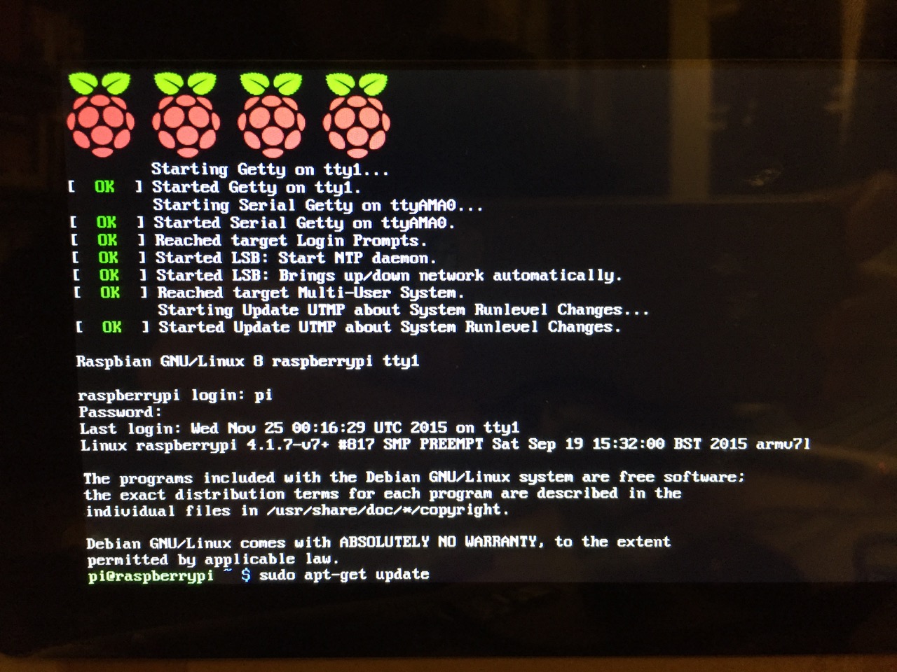
Before setting up the 7″ Touchscreen Display, we need to update Raspbian. To do this, first type: “sudo apt-get update”. If prompted to install anything because it will take a certain amount of space, simply type “y” and press “Enter”.
Entering a command at the prompt in Raspbian’s CLI.
To explain what this command means, “sudo” runs a command as superuser, or the user that is all powerful on a linux system. The command that you want to run as superuser is “apt-get,” which is a package manager, or a manager of software packages that run on your Raspberry Pi. “update” is a modifier for “apt-get,” and its purpose is to tell “apt-get” to update its index of available software packages with what is stored on the remote software repository (where your Raspberry Pi is downloading its software from).
After the update operation completes and you return to the command prompt, type: “sudo apt-get upgrade”. Similarly, agree to the prompts with “y” and “Enter”. The “upgrade” modifier to “apt-get” tells it to upgrade the software based on what it learned when updating its index with the previous command. Thus, when you run these two commands, you should run the update command first (learn) and the upgrade command second (act on what was learned).
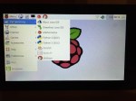
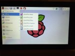
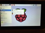
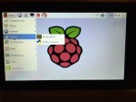
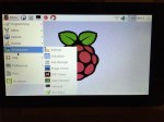
To launch into Raspbian’s X11, type “startx”. Inside X11 or xwindows, you will find many of the GUI-based software that really makes the Raspberry Pi sing: Scratch, Python, Mathematica, and more. If you have never used X11, it works a lot like Windows 95/98 except that the Start Menu bar is at the top of the screen instead of at the bottom and “Start” is replaced by “Menu.” Some quick launch apps are directly available to be launched with a single click from the start bar (such as Terminal, the Epiphany web browser, and Wolfram Mathematica) while all of the installed X11 programs are available from the “Menu.” Below are images of the Raspbian desktop and navigating through some of the default programs available.
To easily install additional software, you can install the Synaptic Package Manager, which simplifies finding and installing software packages by wrapping package management in an easy-to-use GUI. From inside X11, open Terminal and type “sudo apt-get install synaptic”. This will install Synaptic, which you can open by clicking on Menu > Preferences > Synaptic Package Manager (more info on this and other Raspberry Pi stuff on Neil Black’s website).
When you done browsing around, you can click on the and choose to shut down. After a few moments, your display should show a blank screen and the activity lights on the back of the Raspberry Pi (red and green) should only be showing a solid red. At that point, unplug the micro USB 5v power adapter. If you are ready to install the 7″ Touchscreen Display, unplug the HDMI cable, too.
In the images below, I demonstrate how to assemble the 7″ Touchscreen Display and connect it to the Raspberry Pi. I followed the excellent instructions available on the official Raspberry Pi website, which also details how to install the Matchbox virtual keyboard for using the touchscreen without a keyboard.
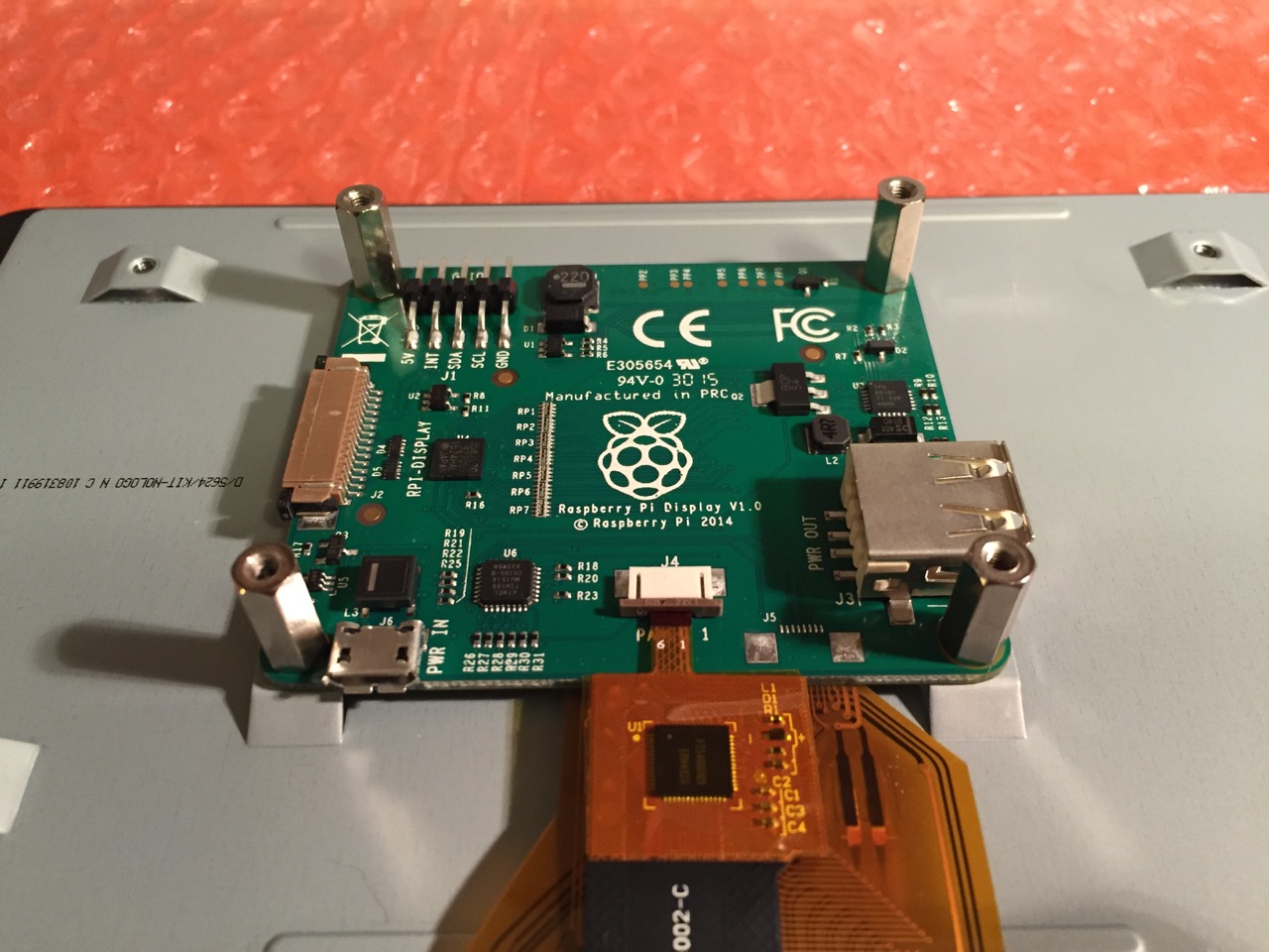
To begin connecting the 7″ Touchscreen Display to the Raspberry Pi, place the screen facing down.
Screw in the standoff posts to hold the display controller card to the display. Connect the display and touchscreen wires as described on the official installation guide.
Insert the display cable to the video input on the controller card.
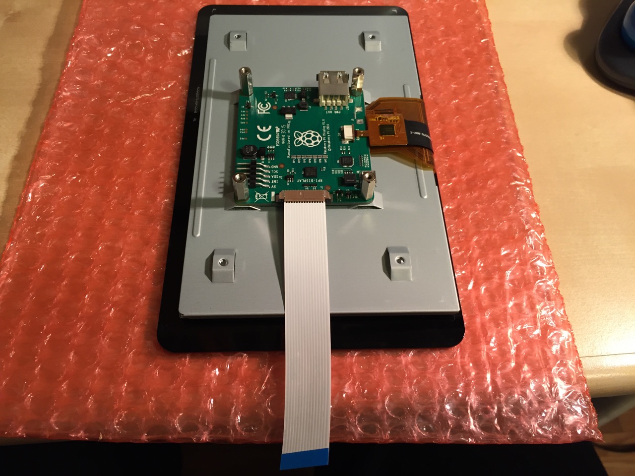
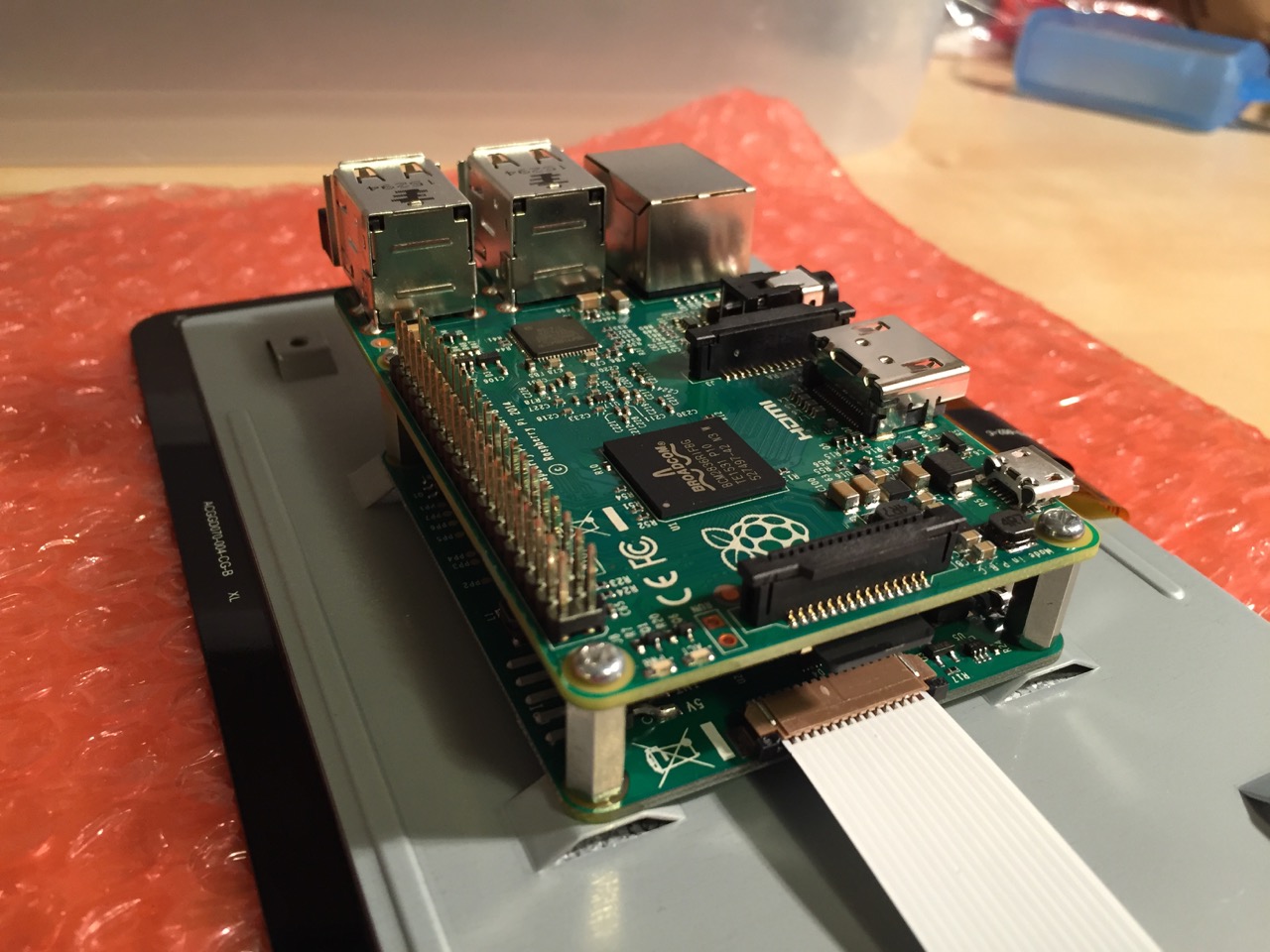
Place the Raspberry Pi above the display controller card and attach with the supplied screws that screw into the top of the standoff posts.
Connect the other end of the display cable into the output connector on the Raspberry Pi.
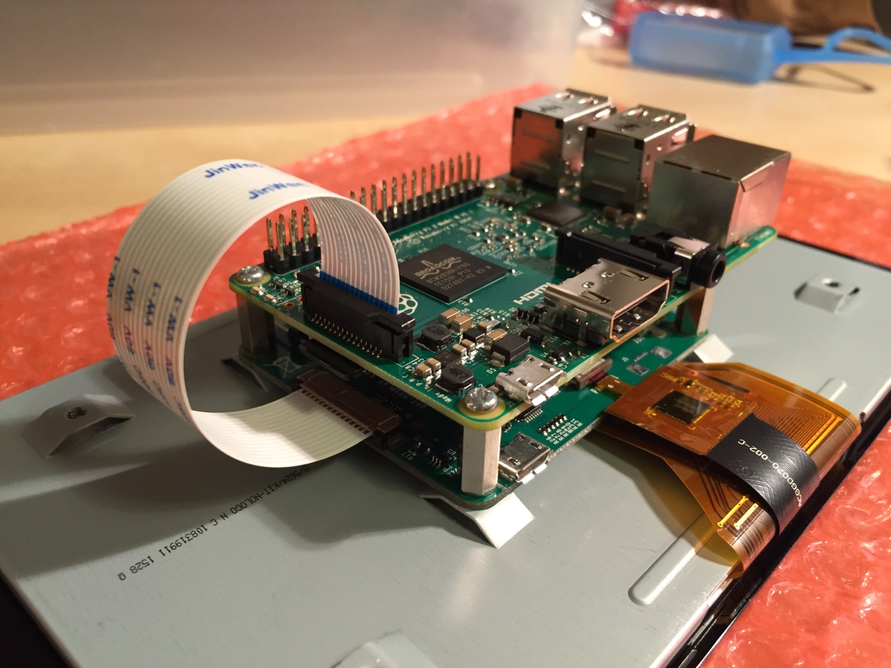
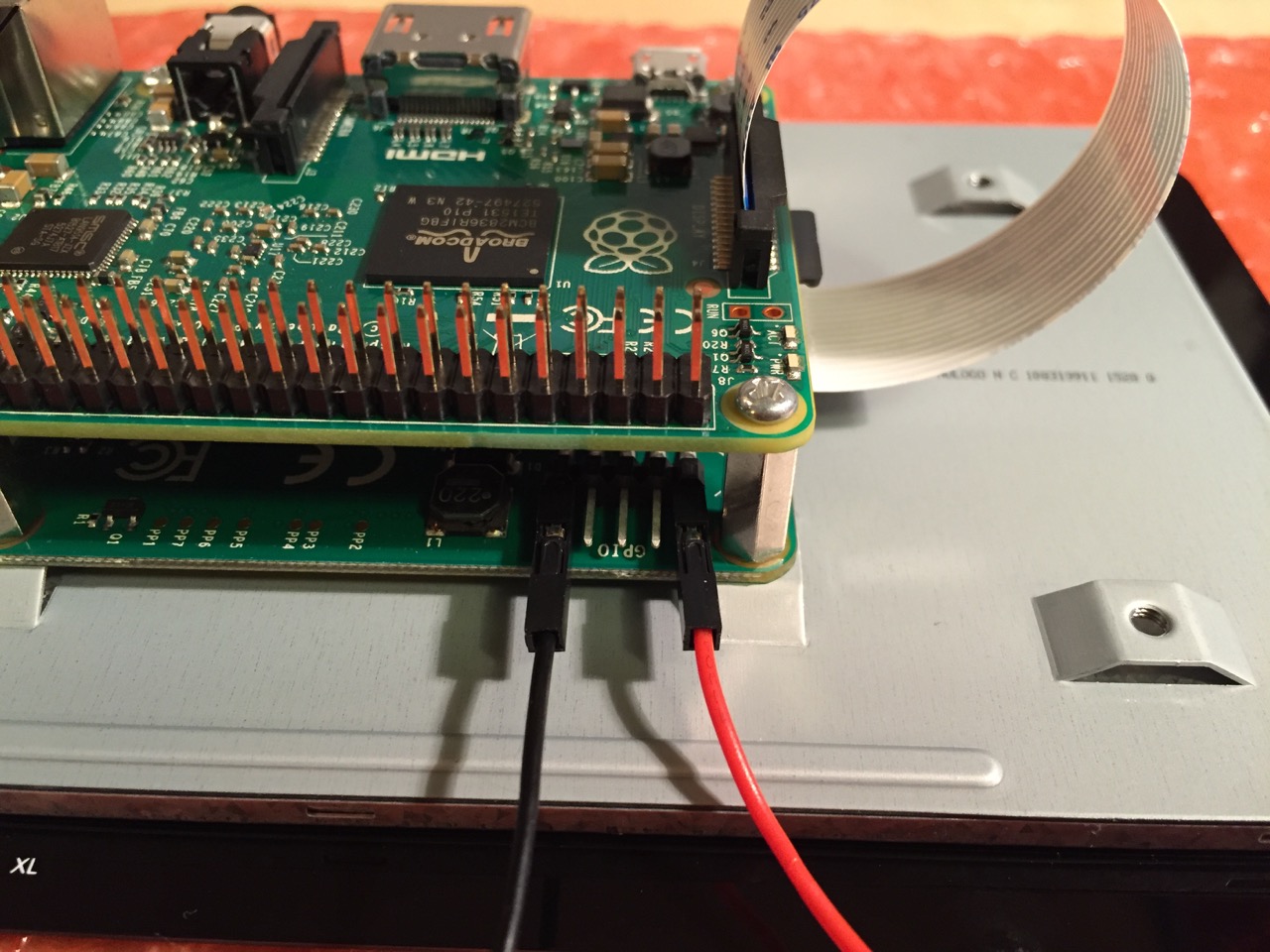
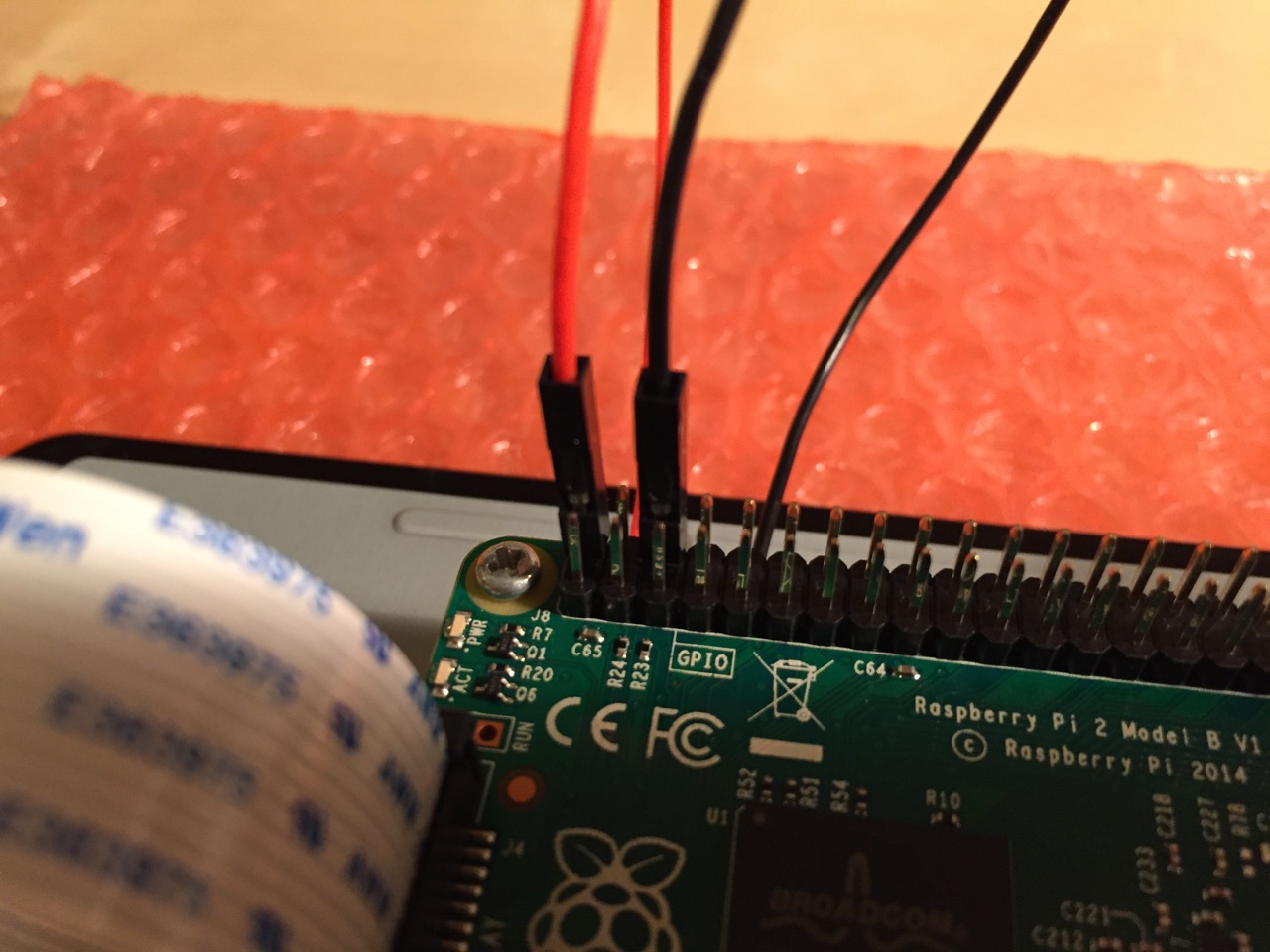
Use the supplied jumper wires to connect connect the power input of the display controller card…
…to the power output leads on the GPIO pins on the Raspberry Pi. This is one of three possible powering configurations–the other two involve USB.
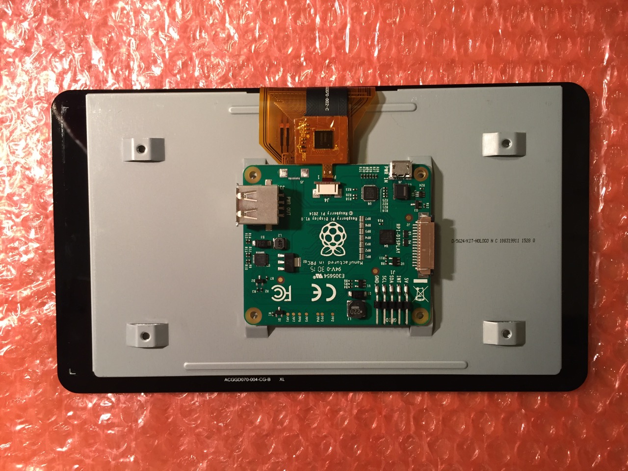
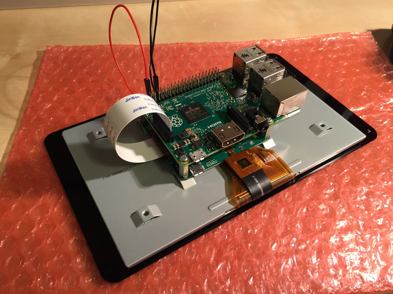
This is the rear of the 7″ Touchscreen Display assembled with the controller card and Raspberry Pi.
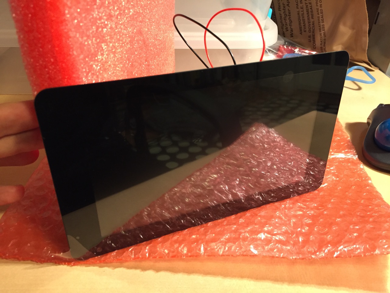
This is the front of the 7″ Touchscreen Display with the power leads sticking out from behind.
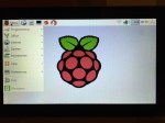
This is the Raspberry Pi powered up again with the 7″ Touchscreen Display.
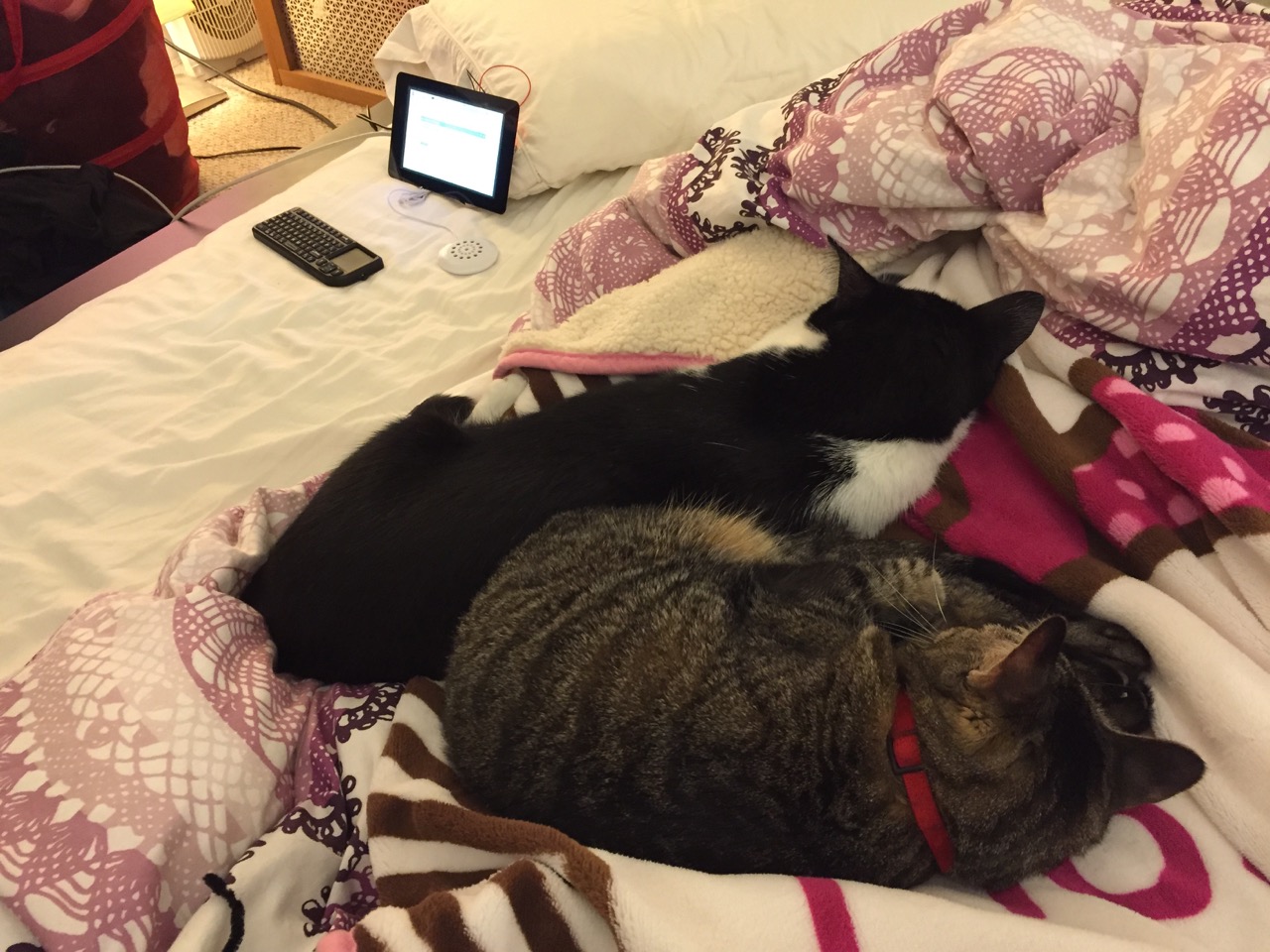
Mose and Miao had lost interest in the project by this point.
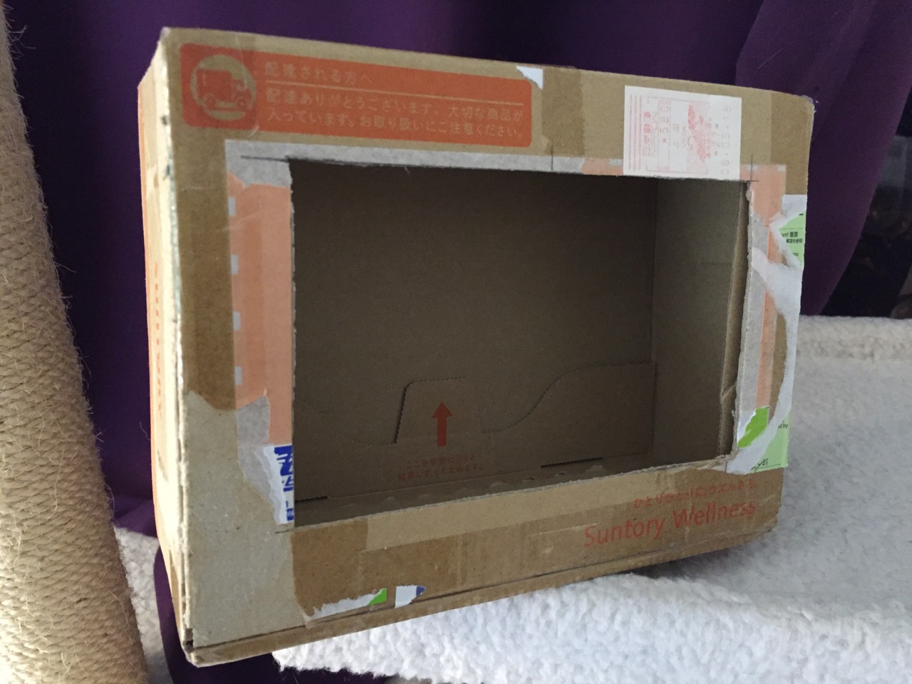
To complete the project, I cut a hole into a Suntory shipping box from Japan that is the exact same size as the 7″ Touchscreen Display box, which would work well, too. It is works well for holding up the Raspberry Pi and storing its accessories when I go between home and work.
Of course, you can use the Raspberry Pi with or without a case depending on your needs. I used the Suntory cardboard box from Japan for practical reasons (thinking: William Gibson: “the street finds its own use for things”–it’s a good size, on-hand, and looks cool) and research reasons (thinking about my work on proto-cyberpunk and the hidden nature of computing, which is an idea explored in my previous blog post about the poster that I created for the 13th annual City Tech Poster Session).
I have run the computer and touchscreen from the 5v battery that I purchased from Tinkersphere, but I get a graphics warning that the Raspberry Pi is under voltage (a rainbow pattern square persists in the upper right corner of the display whether in the CLI or xwindows). I might get a second battery to run the display alone, which would help me troubleshoot if the battery that I have now is actually outputting enough voltage and amperage needed by the Raspberry Pi alone. In the meantime, I am running everything at my desk with the 5v power adapter, which provides ample power for the Raspberry Pi and 7″ Touchscreen Display.
In the future, I would like to use the Raspberry Pi in a writing or technical communication course. There are many ways to leverage the technology: problem solving, writing about process, creating technical documents such as reports and instructions, using the Raspberry Pi as a writing/multimodal composing platform, digital storytelling with tools that come with the Raspberry Pi, and more. These ideas are built only around the Raspberry Pi and its software. A whole other universe of possibilities opens up when you begin building circuits and integrating the Raspberry Pi into a larger project.
The basic cost of entry with the platform is $30 for the Raspberry Pi 2, Model B and a few dollars for an 8GB micro SD card. If you have access to a display with HDMI, a USB keyboard and mouse, and ethernet-based Internet access, you can get started with Raspberry Pi almost immediately. For a future grant application, I am imagining a proposal to purchase the basic needed equipment to use Raspberry Pi in an existing computer lab. I can bring the kits to each class where students can use them on different assignments that meet the outcomes for that course but in an engaging and challenging way that I think they would enjoy and would be beneficial to them in ways beyond the immediate needs of the class.
On this last point, I am thinking of working with digital technology in an a way many of my students will not have had a chance to before, feeling a sense of accomplishment, learning from one another on team-based projects, experiencing a sense of discovery with a computing platform that they might not have used before, and of course, communicating through the process of discovery in different ways and to different audiences. This might be something that you’re interested in, too. Drop me a line if you are!
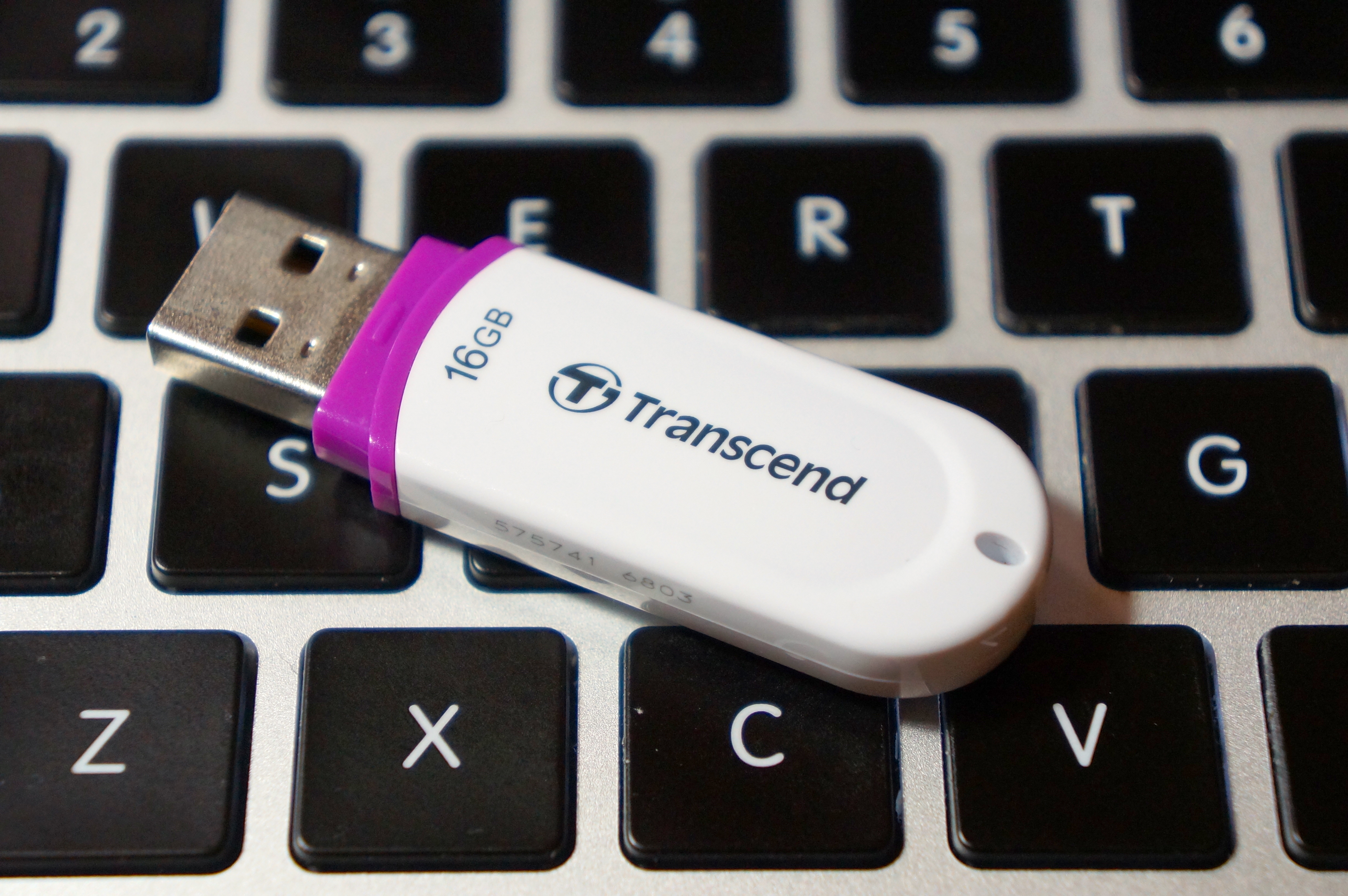
16 GB Transcend Flash Drive from NOVA in Taipei, Taiwan
My friend sent me a link to a video by someone who turned an older Core2Duo-based Dell Optiplex into a Hackintosh. The video convinced me to do something that I had been meaning to do for a long time but had never got around to actually doing: removing Windows 7 on my ASUS P8Z77-V/Intel i7-based PC that I built late last year and installing Mac OS X 10.8.
A Hackintosh, or what some folks call a CustoMac, is a standard PC that runs one of the Intel-based version of Mac OS (this includes 10.4 Tiger, 10.5 Leopard, 10.6 Snow Leopard, 10.7 Lion, and 10.8 Mountain Lion).
Prior to this project, I had purchased Mountain Lion from the MacApp Store for my old MacBook 5,1 (Aluminum Unibody, Late-2008). When my parents gifted me a rMPB, it already had Mountain Lion installed. This gave me the needed components that I needed to setup my flash drive to install Mac OS on my PC: a Mac and a purchased copy of Mountain Lion.
According to the definitive source for creating CustoMacs, TonyMacx86, my hardware isn’t ideally suited for a pain-free installation (If you are beginning from scratch, you should check out TonyMacx86’s excellent buyer’s guide here). Nevertheless, I worked my way through six re-installations before discovering the combination of settings that yielded a reliable and stable Mountain Lion installation.
evga 01G-P3-1561-KR GeForce GTX 560 Ti 1024MB GDDR5 PCIe 2.0 x16 Video Card
Antec High Current Gamer 750W Gamer Power Supply HCG-750
Corsair Vengeance C70 Gaming Mid Tower Case Military Green
Cooler Master Hyper 212 Plus Universal CPU Cooler
Samsung 22X DVD±RW Burner with Dual Layer Support – OEM
Intel 128 GB SATA SSD
Western Digital Caviar Green WD10EARX 1TB IntelliPower 64MB Cache SATA 6.0Gb/s 3.5″ Internal Hard Drive – Bare Drive
These are the steps that led to my successful Mountain Lion installation:
Follow TonyMacx86’s UniBeast (the software that prepares your installation media) and Mountain Lion installation guide here. I have modified the instructions below to reflect what I did after creating my bootable flash drive containing the Mountain Lion installer and a folder that I made containing MultiBeast (the software that configures your Mountain Lion installation for your computer’s hardware). (Depending on your needs, you might need other software, including MaciASL, which can create a DSDT file–another kind of configuration file for MultiBeast that gives Mac OS the information that it needs to run well on your hardware. You will need to configure it with sources from PJALM’s DSDT Patch Repositories. Ultimately, I decided to proceed with a DSDT-free installation.)
Turn on the PC with the flash drive inserted on one of the front mounted USB 3.0 slots.
Press F8 to select bootup device and select the flash drive.
Chimera, the bootloader software, provides you with an option to select the flash drive’s Mac OS installation to boot. If you press the down arrow key on the keyboard, you will be presented with other options including help. If you begin typing, you can enter commands to assist with booting the installer.
On the Chimera boot selection screen, type “PCIRootUID=0”. Press Enter. This ensures that the installer’s Mac OS installation will display video correctly. Without this option, the screen goes dark after the Apple logo over gray screen.
From the Mac OS installer menu bar, select Utilities > Disk Utility > Format your boot drive for Mac OS Extended, Journaled. Close the Disk Utility window to return to the installer. Proceed with installation. Reboot when completed.
Press F8. Select the flash drive. At the Chimera screen, select your internal hard drive’s new Mac OS Mountain Lion installation, type in “PCIRootUID=0”, and press Enter.
Mountain Lion will boot from your hard drive and begin the setup procedure (choosing location, creating your Admin account, etc.).
If you have already downloaded MultiBeast and placed it in a new folder on your flash drive, open your flash drive from the Desktop, navigate to MultiBeast, and launch it.
Proceed to the selection screen and check these things:
Drivers & Bootloaders > Drivers > System > Patched AppleIntelCPUPowerManagement > OS X 10.8.x
Complete installation and close MultiBeast.
Navigate to Applications > Utilities > Disk Utility. Select your hard drive and click Repair Permissions. When completed, close Disk Utility, eject your flash drive and remove from the USB port, and reboot.
When back at the Desktop, go to System Preferences > Energy Saver > Disable Computer Sleep by sliding the widget to the far right.
Plug your computer into your router with an ethernet cable if you have not already done so. You can easily get online with the wired connection.
Your installation is complete!
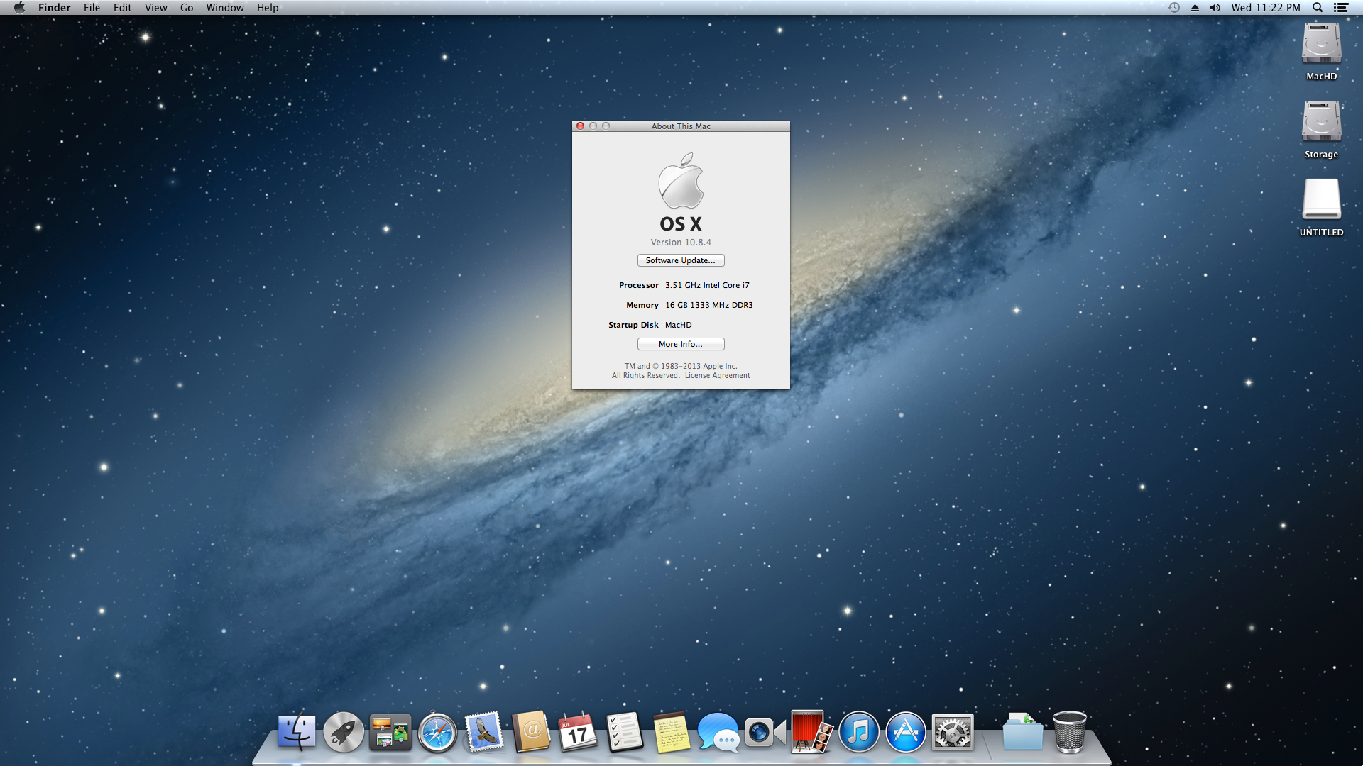
Mac OS X 10.8.4 desktop showing CPU and memory. Everything is running a-okay!
I chose to go this route, because I could not get Mac OS to boot with the DSDTs that I created with MaciASL (using the configuration for the P8Z77-V motherboard and graphics source per PJALM’s instructions). My problems could have been related to the DSDT or due to incompatibilities between its settings and my P8Z77-V’s BIOS ROM version (I was unable to use the motherboard’s BIOS Flashback feature to successfully load one of these hacked BIOS ROMs on this site). Apparently, if you can get the DSDT to install correctly and have the hacked BIOS, you will be able to enjoy power management settings and control. Since I have my computer only on when I am using it, I do not have any problem with this lack of functionality. Since installation, my Hackintosh has been running great. It is snappy, video and sound work great, network connectivity is fine, and Doom 3 plays fantastically at 1080p!
After the installation, I discovered one tremendous problem: FileVault cannot be activated for your boot drive. Apparently, this is due to FileVault needing a real Mac’s EFI environment (or the error message that it generates indicates that it has to do with its inability to re-partition the bootdrive–likely due to the Chimera bootloader). As far as I can tell from reading posts on the TonyMacx86 forums, there is no way around this problem. One option would be to save your files in a TrueCrypt container or fully encrypted drive that is separate from your bootdrive. Another way is to use TrueCrypt full disk encryption as detailed on this helpful blog post from Frugal Computing (FC also has some great articles about building Hackintoshes).
Others in the TonyMacx86 forums have had varying levels of success with the Asus P8Z77-V and Mountain Lion, so I do not want to dissuade you from attempting to get more functionality on your installation. The above is simply a report of what worked for me. It might work for you, and it might give you a beginning for your own Hackintosh project.