Before Thanksgiving 2016, I purchased an Intel NUC 6I5SYH ($319.99 on sale at Microcenter, late-November 2016) to serve as my new home desktop computer. This review/guide is based on my initial setup of the 6I5SYH.
The Intel NUC 6I5SYH is a small form factor (SFF) bare-bones personal computer from Intel’s “Next Unit of Computing” line.
The 6I5SYH includes an enclosure (approximately 4 1/2″ wide x 4 3/8″ deep x 2″ tall), motherboard with a soldered i5-6260U CPU (Skylake, or 6th-gen architecture–1.9GHz up to 2.8GHz Turbo, Dual Core, 4MB cache, 15W TDP), wall-mount power adapter with multi-country AC plugs, and VESA mount bracket.
The 6I5SYH’s motherboard supports the i5’s integrated Iris 540 graphics over a built-in HDMI 1.4b or Mini DisplayPort 1.2, and it includes 2x USB 3.o ports (back), 2x USB 3.0 ports (front and one supports charging), 2x USB 2.0 headers (on motherboard), IR sensor, Intel 10/100/1000Mbps ethernet, Intel Wireless-AC 8260 M.2 (802.11ac, Bluetooth 4.1, and Intel Wireless Display 6.0), headphone/microphone jack (front, or 7.1 surround sound via HDMI and Mini DisplayPort/back), and SDXC slot with UHS-I support (left side).
The 6I5SYH requires the user to supply a hard drive or SSD, and RAM. For permanent storage, it has internal support for an M.2 SSD card (22×42 or 22×80) and SATA3 2.5″ HDD/SSD (up to 9.5mm thick). For memory, it supports dual-channel DDR4 SODIMMs (1.2V, 2133MHz, 32GB maximum) across two internal slots.
For my 6I5SYH’s RAM, I installed one Crucial 8GB DDR4 2400 BL SODIMM ($44.99 on sale at Micro Center, late-November 2016), and for its SSD, I installed a Silicon Power S60 240GB SATA3 SSD ($67.99 on sale on Amazon, December 2015). Excluding the costs of a monitor, keyboard, and trackball, this system cost $432.97.
After first assembling the 6I5SYH with its RAM and SSD, I booted it and went into the BIOS (press F2 at the boot/Intel screen) to check its BIOS version. Based on everything that I had read about this and past Intel NUCs, it is always advisable to have the most up-to-date BIOS installed. Sure enough, it reported having BIOS 0045, and a newer BIOS had been released (0054) according to the Intel Download Center page for the 6I5SYH.
I downloaded the new BIOS binary file to a FAT-formatted USB flash drive on my Mac, inserted the USB flash drive into a front USB port on the NUC, pressed F7 to update BIOS, and followed the prompts. After confirming the BIOS had updated, I turned the 6I5SYH off by holding down the power button on its top plate.
After the media creation was completed, I inserted my Fedora 25 bootable USB flash drive into a front USB port of the 6I5SYH, powered it on, pressed F10 for the boot menu, and followed the prompts. If you need an installation guide for Fedora 25 check out the Fedora Documentation here, or if you need a screenshot walkthrough of installing Fedora 25, check out this guide.
After installing Fedora 25 with full disk encryption, I installed updates and began installing additional software. The guides here and here offer great advice (there are others for “what to do after installing fedora 24” that have useful info, too) on what to install and configure after a fresh installation of Fedora. Some that I recommend include Gnome Tweak Tool (available within Software app), Yum Extender (DNF) (available within Software app), VeraCrypt, and VLC. Remember to install RPM Fusion free and nonfree repositories–directions here, too.
So far, Fedora 25 has performed wonderfully on the 6I5SYH! Out of the box, the graphics, WiFi, Bluetooth, USB ports, and SD card reader have worked without error. I am using a Mini DisplayPort to VGA adapter to connect the 6I5SYH to a less expensive VGA-input LCD monitor. I am watching 1080p Rogue One trailers without a hiccup, and I listen to Beastie Boy MP3s while doing work in GIMP or LibreOffice. I have not yet fully tested virtualization or emulation (consoles or vintage computing)–these are my next steps.
The 6I5SYH is snappy about doing work, and it is quiet nearly always except when it first boots up (and the fans spin up high momentarily). For the features, size, and price, I highly recommend the 6I5SYH as a desktop replacement that runs Fedora 25 and common Linux programs quite well!
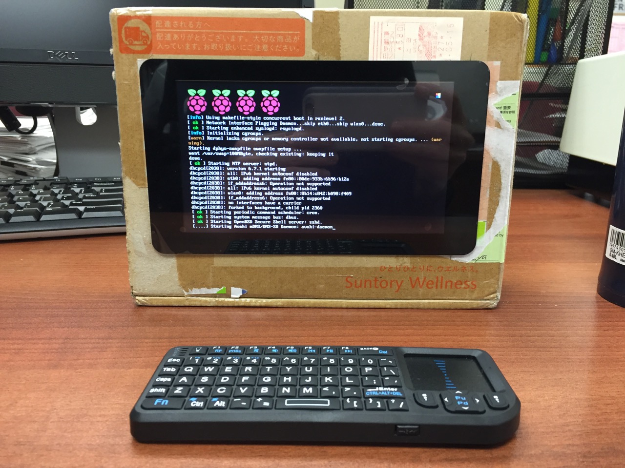
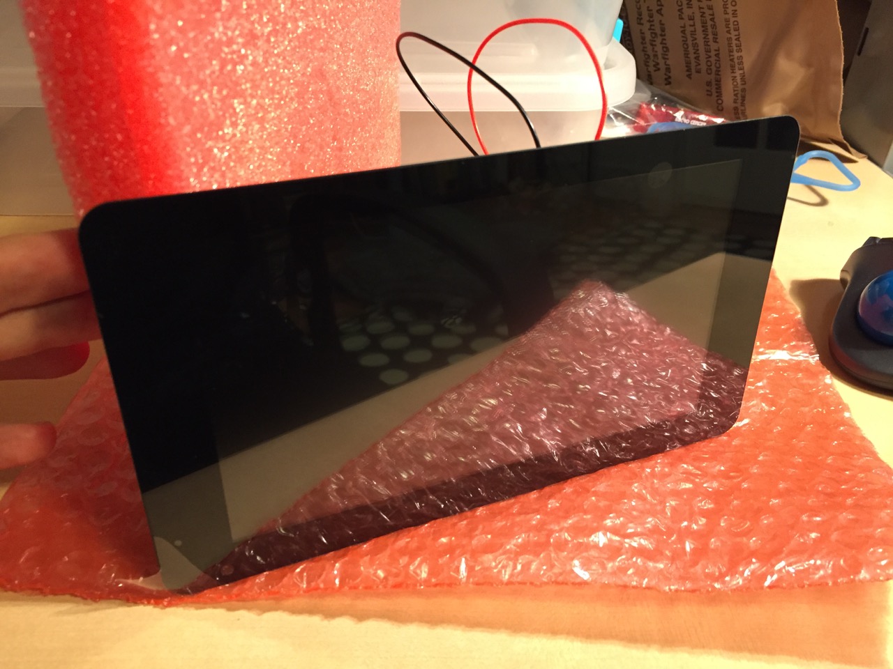
My Cardboard Box Raspberry Pi 2, Model B with 7″ Touchscreen Display and wireless keyboard.
This guide demonstrates how to install Raspbian on a Raspberry Pi 2, Model B, connect the Raspberry Pi to a 7″ Touchscreen LCD, and integrate the computer and touchscreen in a cardboard box (which doubles as a case and storage for battery, keyboard, and cables).
I got interested in the Raspberry Pi, because it has many capabilities for learning: kitting out a computer, installing a Linux-based operating system, programming interactive software, and building with electronics. In particular, I am interested in how the Raspberry Pi can be used to create interactive software and be a platform for digital storytelling (which figures into one of the upcoming classes that I will be teaching at City Tech–ENG 3760 Digital Storytelling).
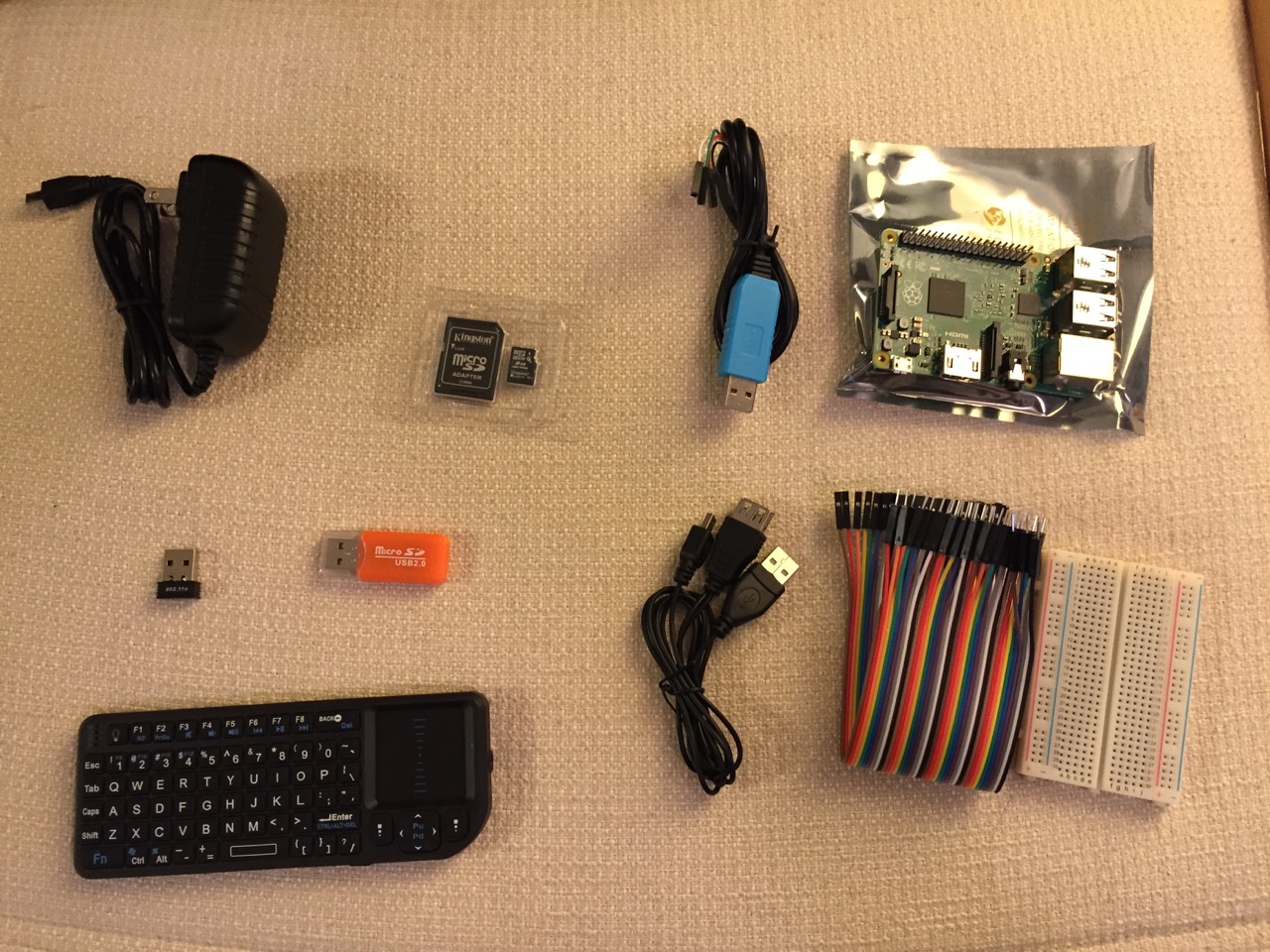
My haul from Tinkersphere.
Instead of buying my kit online, I wanted to shop local to get started. Originally, I considered going to Microcenter, which is near where I live in Brooklyn. Unfortunately, they were sold out of the touchscreen display that I wanted. Instead, Y and I took a train into Manhattan and visited Tinkersphere where one of their helpful staff guided me to the things on my digital grocery list. I purchased Tinkersphere’s pre-made Raspberry Pi 2 kit, a 7″ Touchscreen LCD display, a battery pack (in retrospect, I should have purchased two of these, which I will discuss below), and a mono speaker with 1/8″ plug.
Contents of Tinkersphere’s Raspberry Pi 2, Model B kit.
Tinkersphere’s Raspberry Pi 2, Model B kit includes all of the basic equipment needed to begin working with this tiny computing platform. The kit is built around the Raspberry Pi 2, Model B computer with a 900MHz quad-core ARM Cortex-A7 CPU, 1GB RAM, 4 USB ports, 40 GPIO pins, HDMI port, ethernet port, combined 3.5mm audio jack and composite video, camera interface (CSI), display interface (DSI), micro SD card slot, and a VideoCore IV 3D graphics core. Additionally, the kit includes a wireless keyboard/trackpad, USB wifi adapter, 8GB micro SD card with NOOBS (the easy to use Raspbian installer), USB micro SD card reader, breadboard, wires, and 5v power supply.
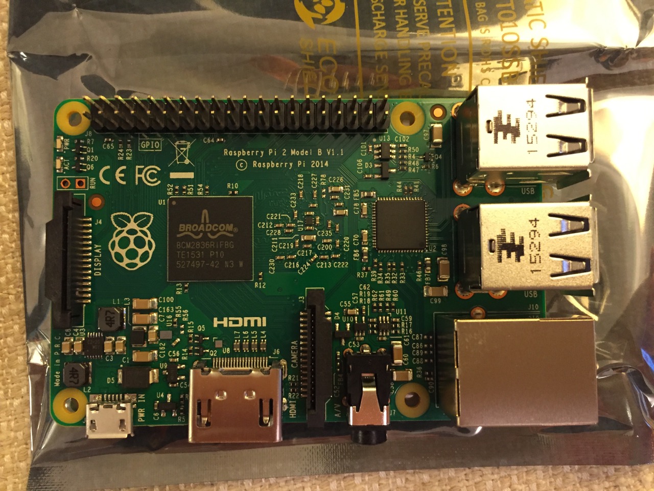
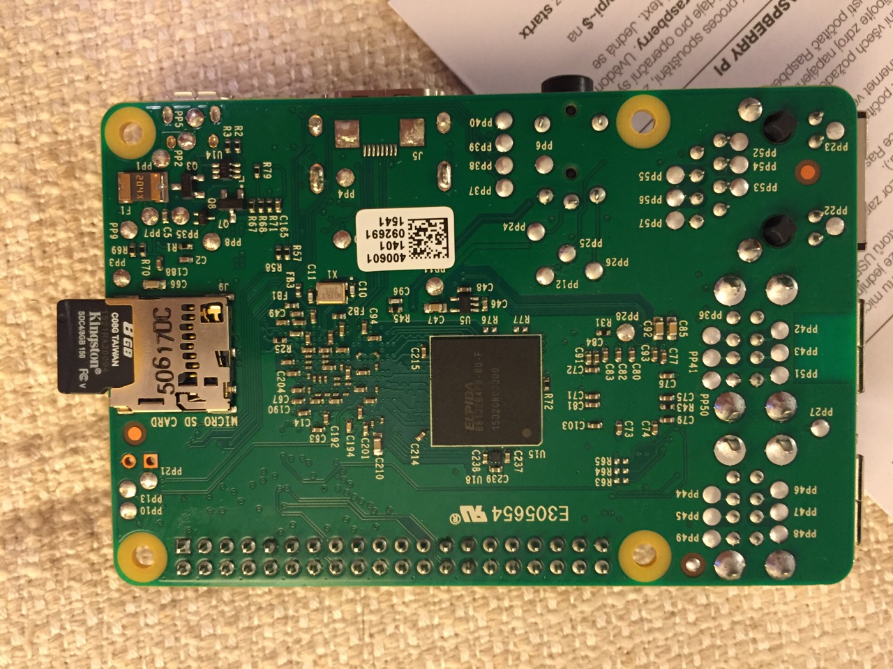
To begin the setup, we should orient ourselves with the Raspberry Pi. This is the Raspberry Pi 2, Model B computer viewed from the top and the bottom:
Raspberry Pi 2, Model B, Top View.
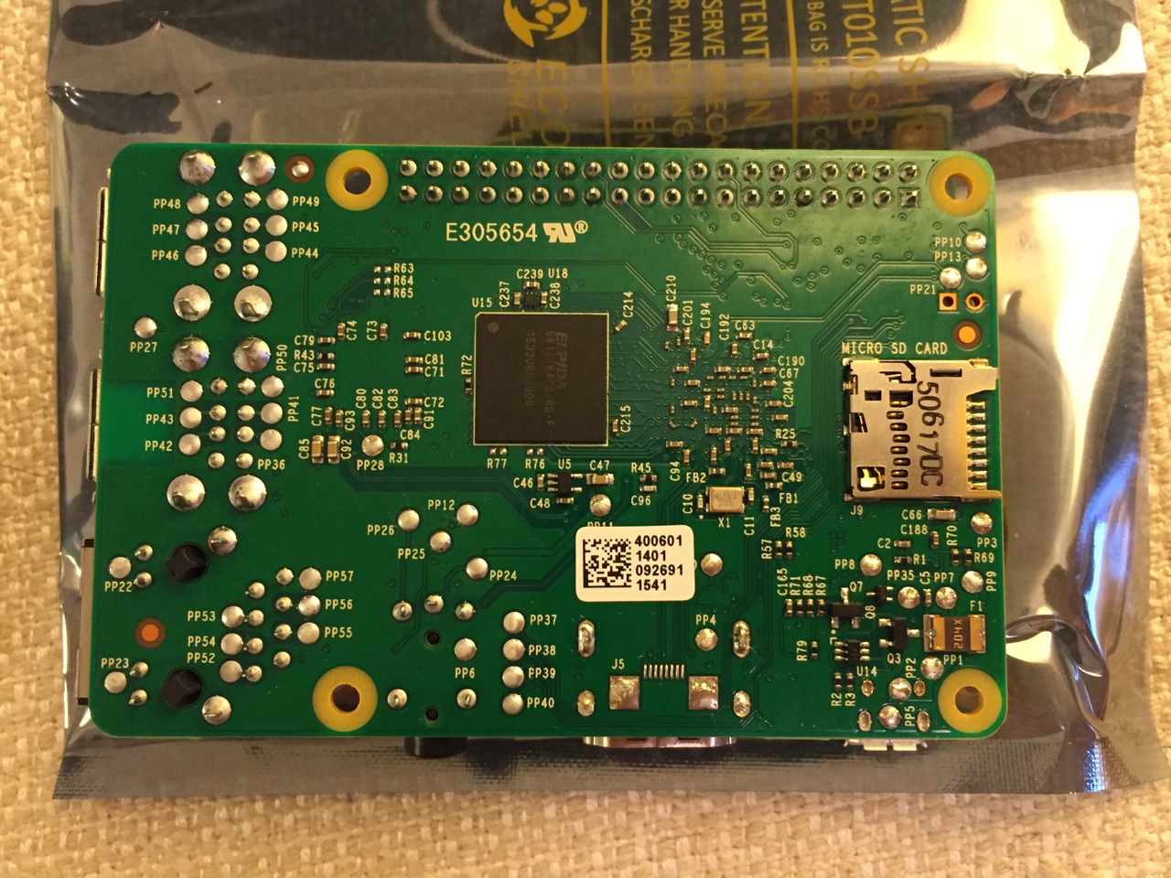
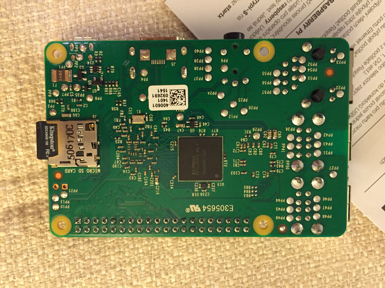
Raspberry Pi 2, Model B, Bottom View.
The first thing that we need to do is insert the micro SD card with a copy of NOOBS pre-copied. If you need a copy of NOOBS for your own micro SD card, you can download it from here and follow the instructions here for formatting and copying the files from a Mac or PC to the micro SD card. The Raspberry Pi’s micro SD card slot is located on the bottom side of its circuit board. A micro SD card goes in only one way which allows you to press it in. If correct, the card should “click” and stay as seen in the photos below.
Insert the micro SD card like this.
Press the micro SD card in and it will stay in place with a “click.”
The Raspberry Pi connected from left to right: micro USB power input from 5v power supply, HDMI, wireless keyboard/trackpad receiver, and wifi adapter.
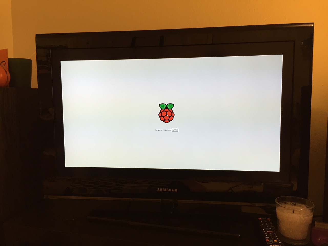
Next, connect the Raspberry Pi to a display (such as a TV) with HDMI, and plug in the wifi adapter and wireless keyboard into two available USB ports. Alternatively, you can connect the Raspberry Pi to the Internet via ethernet and to a wired keyboard and mouse. Then, connect it to the 5v power supply. As soon as it is plugged in, the Raspberry Pi is turned on and operational. It will begin to boot from the micro SD card’s NOOBS installer, which will guide you through the process of installing Raspbian. See the images below to see what this looks like and what choices you should make for a basic installation.
NB: While we could have connected the 7″ Touchscreen Display to the Raspberry Pi before beginning the installation, the current version of NOOBS would not detect and use the touchscreen display. It is necessary for Raspbian to be installed and updated before the 7″ Touchscreen Display will be recognized and used as the Raspberry Pi 2’s primary display.
NOOBS boot screen with the Raspberry Pi logo.
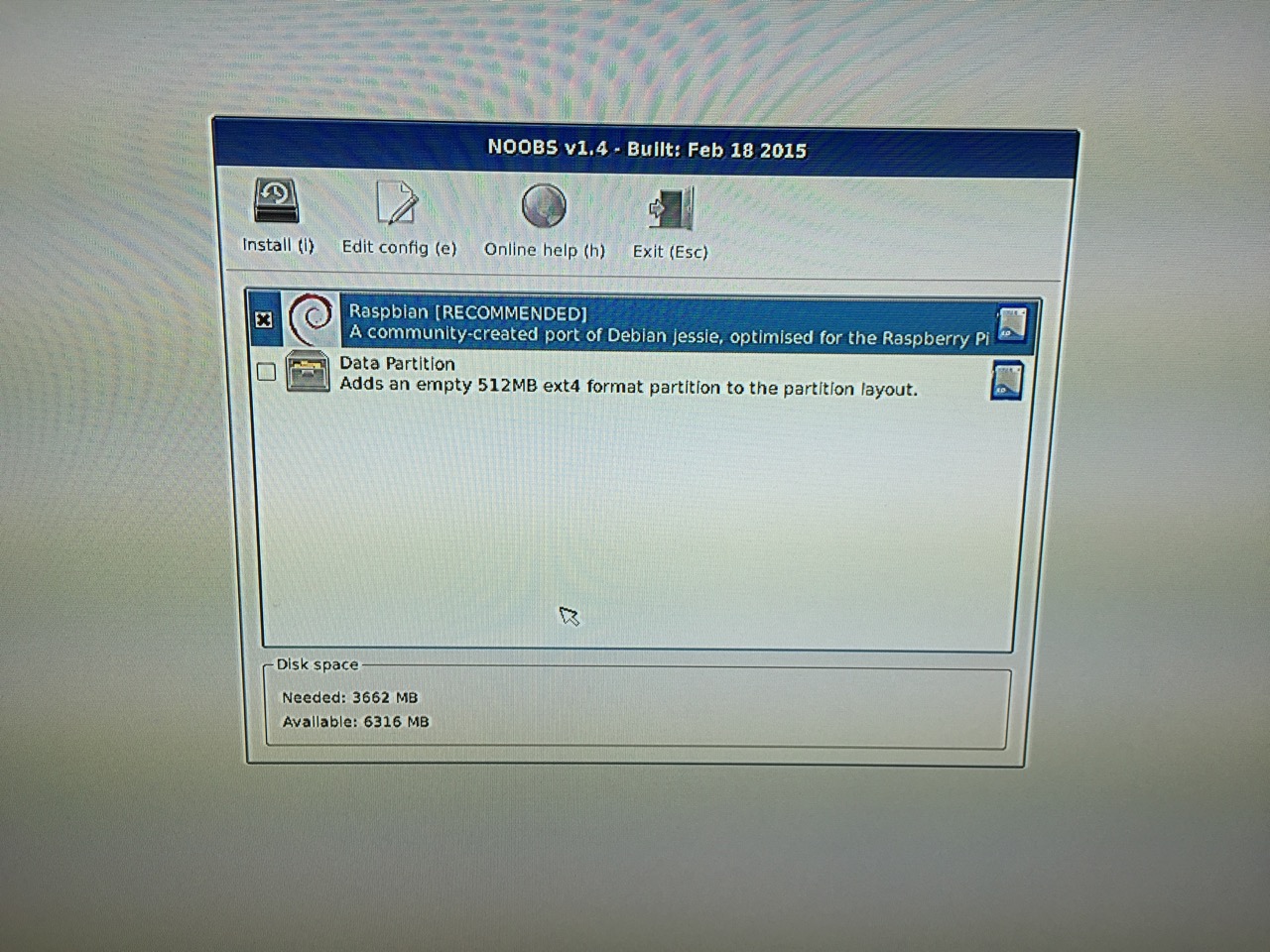
The NOOBS installer asks what you would like installed. Place a check next to Raspbian.
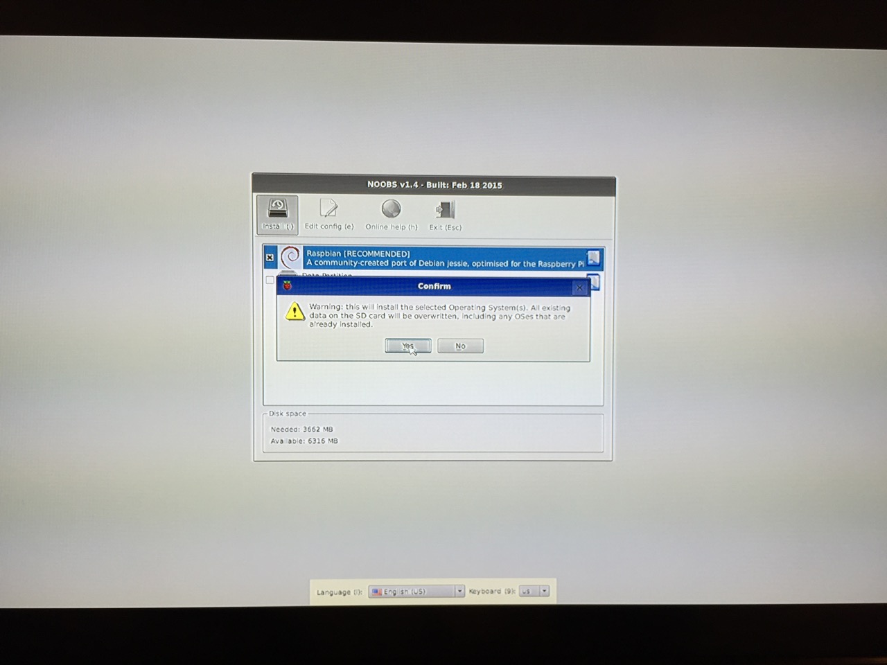
The NOOBS installer will ask that you confirm your choice. If you haven’t already done so, choose US keyboard and locationalization at the bottom of the screen before proceeding. Then, confirm.
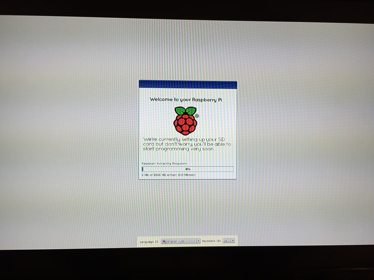
The installation will proceed and complete. With the micro SD card that I have and without overclocking the Raspberry Pi, it took about 20-30 minutes for the installation to complete.
After rebooting following the installation, the raspi-config tool launches. This program gives the user easy access to many configuration options for the Raspberry Pi including how it should boot (automatically login and load xwindows, or boot to a command prompt login), and if you would like to overclock the Raspberry Pi for additional performance (use this option with caution–you will likely want to add heat sinks and increased ventilation if you overclock the system). I configured my Raspberry Pi to operate at normal speed and to boot to the command line with login.
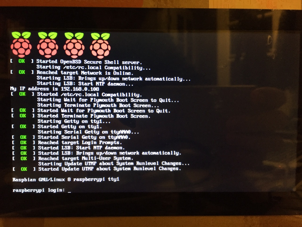
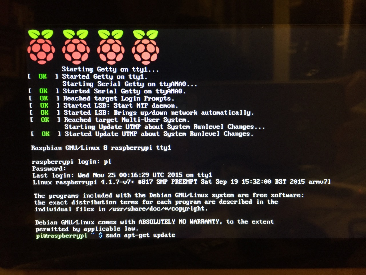
After booting into Raspbian, the first thing that you see is the login prompt.
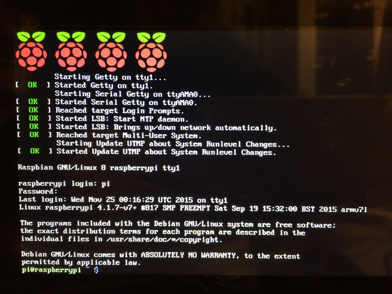
The default login for the Raspberry Pi is username “pi” and password “raspberry”. Type each of these credentials in when asked followed by pressing the Enter key. Then, you will find yourself at the command line interface (CLI).
Before setting up the 7″ Touchscreen Display, we need to update Raspbian. To do this, first type: “sudo apt-get update”. If prompted to install anything because it will take a certain amount of space, simply type “y” and press “Enter”.
Entering a command at the prompt in Raspbian’s CLI.
To explain what this command means, “sudo” runs a command as superuser, or the user that is all powerful on a linux system. The command that you want to run as superuser is “apt-get,” which is a package manager, or a manager of software packages that run on your Raspberry Pi. “update” is a modifier for “apt-get,” and its purpose is to tell “apt-get” to update its index of available software packages with what is stored on the remote software repository (where your Raspberry Pi is downloading its software from).
After the update operation completes and you return to the command prompt, type: “sudo apt-get upgrade”. Similarly, agree to the prompts with “y” and “Enter”. The “upgrade” modifier to “apt-get” tells it to upgrade the software based on what it learned when updating its index with the previous command. Thus, when you run these two commands, you should run the update command first (learn) and the upgrade command second (act on what was learned).
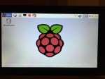
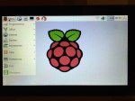
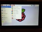
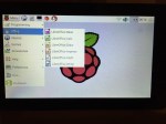
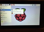
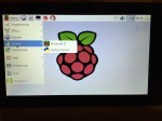
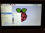
To launch into Raspbian’s X11, type “startx”. Inside X11 or xwindows, you will find many of the GUI-based software that really makes the Raspberry Pi sing: Scratch, Python, Mathematica, and more. If you have never used X11, it works a lot like Windows 95/98 except that the Start Menu bar is at the top of the screen instead of at the bottom and “Start” is replaced by “Menu.” Some quick launch apps are directly available to be launched with a single click from the start bar (such as Terminal, the Epiphany web browser, and Wolfram Mathematica) while all of the installed X11 programs are available from the “Menu.” Below are images of the Raspbian desktop and navigating through some of the default programs available.
To easily install additional software, you can install the Synaptic Package Manager, which simplifies finding and installing software packages by wrapping package management in an easy-to-use GUI. From inside X11, open Terminal and type “sudo apt-get install synaptic”. This will install Synaptic, which you can open by clicking on Menu > Preferences > Synaptic Package Manager (more info on this and other Raspberry Pi stuff on Neil Black’s website).
When you done browsing around, you can click on the and choose to shut down. After a few moments, your display should show a blank screen and the activity lights on the back of the Raspberry Pi (red and green) should only be showing a solid red. At that point, unplug the micro USB 5v power adapter. If you are ready to install the 7″ Touchscreen Display, unplug the HDMI cable, too.
In the images below, I demonstrate how to assemble the 7″ Touchscreen Display and connect it to the Raspberry Pi. I followed the excellent instructions available on the official Raspberry Pi website, which also details how to install the Matchbox virtual keyboard for using the touchscreen without a keyboard.
To begin connecting the 7″ Touchscreen Display to the Raspberry Pi, place the screen facing down.
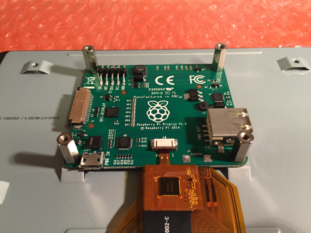
Screw in the standoff posts to hold the display controller card to the display. Connect the display and touchscreen wires as described on the official installation guide.
Insert the display cable to the video input on the controller card.
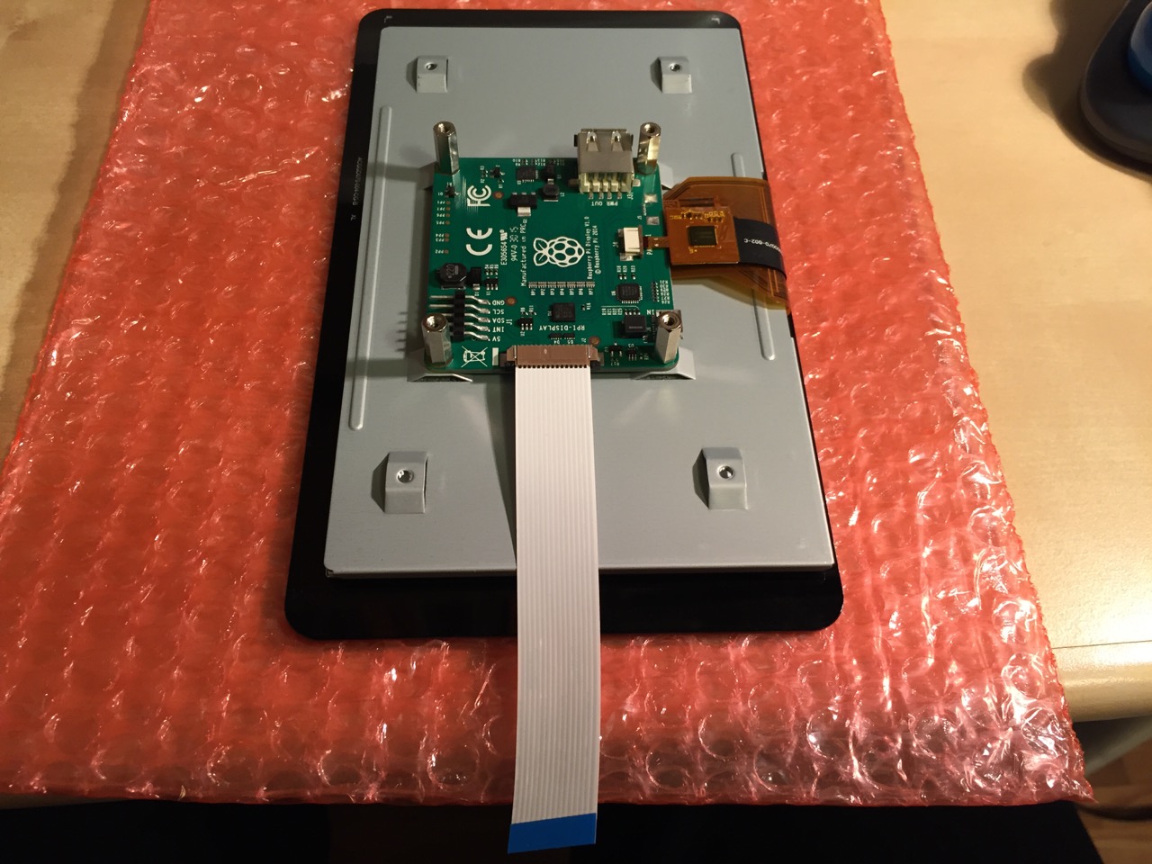
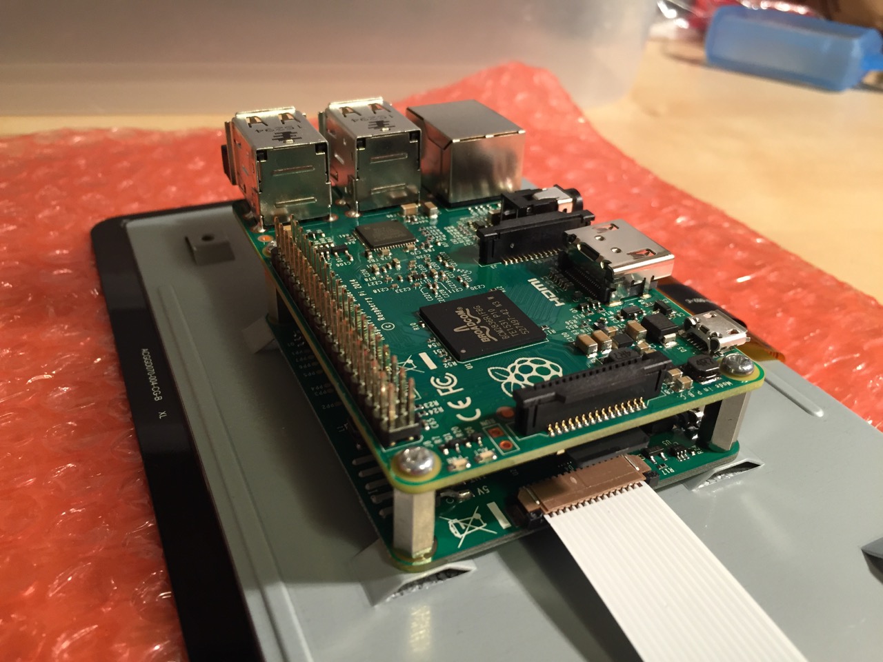
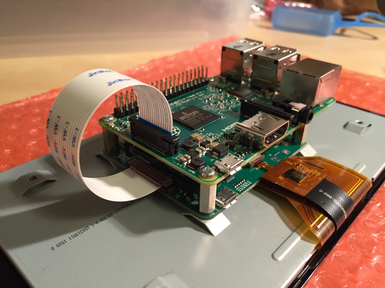
Place the Raspberry Pi above the display controller card and attach with the supplied screws that screw into the top of the standoff posts.
Connect the other end of the display cable into the output connector on the Raspberry Pi.
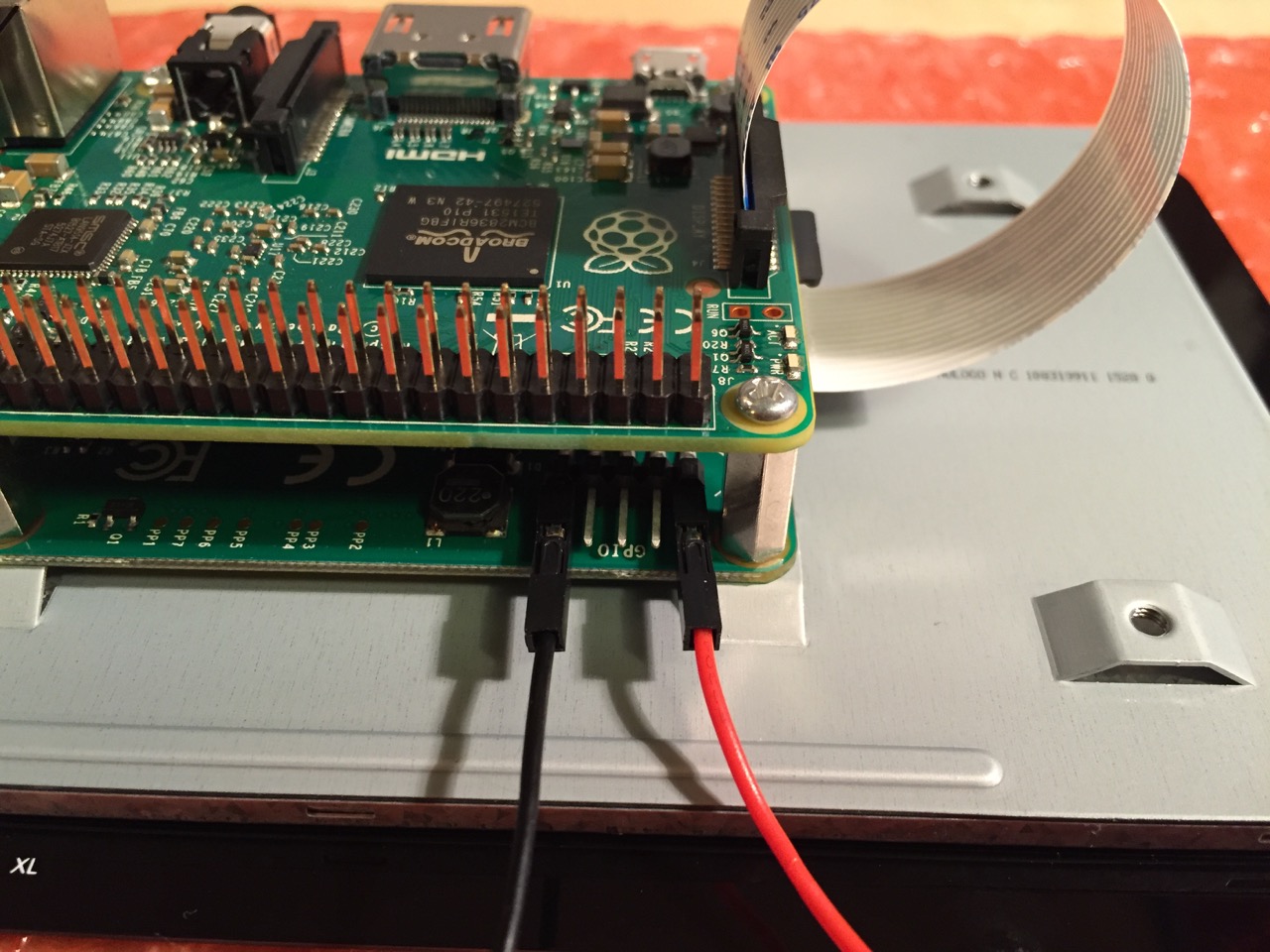
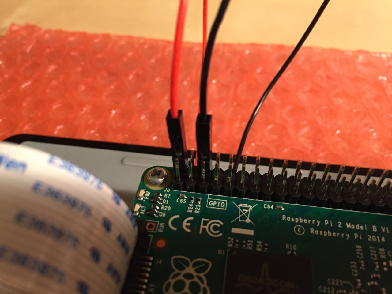
Use the supplied jumper wires to connect connect the power input of the display controller card…
…to the power output leads on the GPIO pins on the Raspberry Pi. This is one of three possible powering configurations–the other two involve USB.
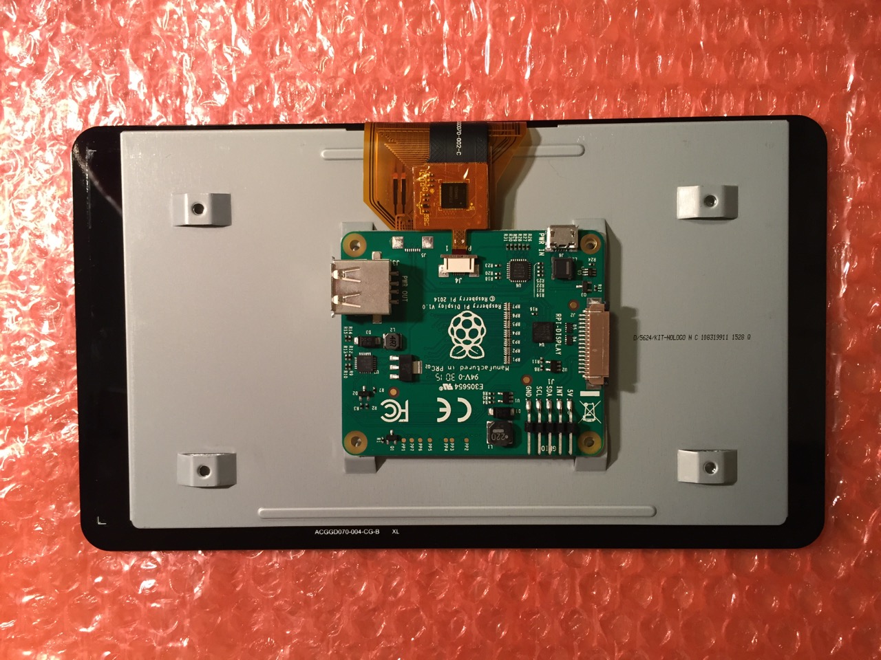
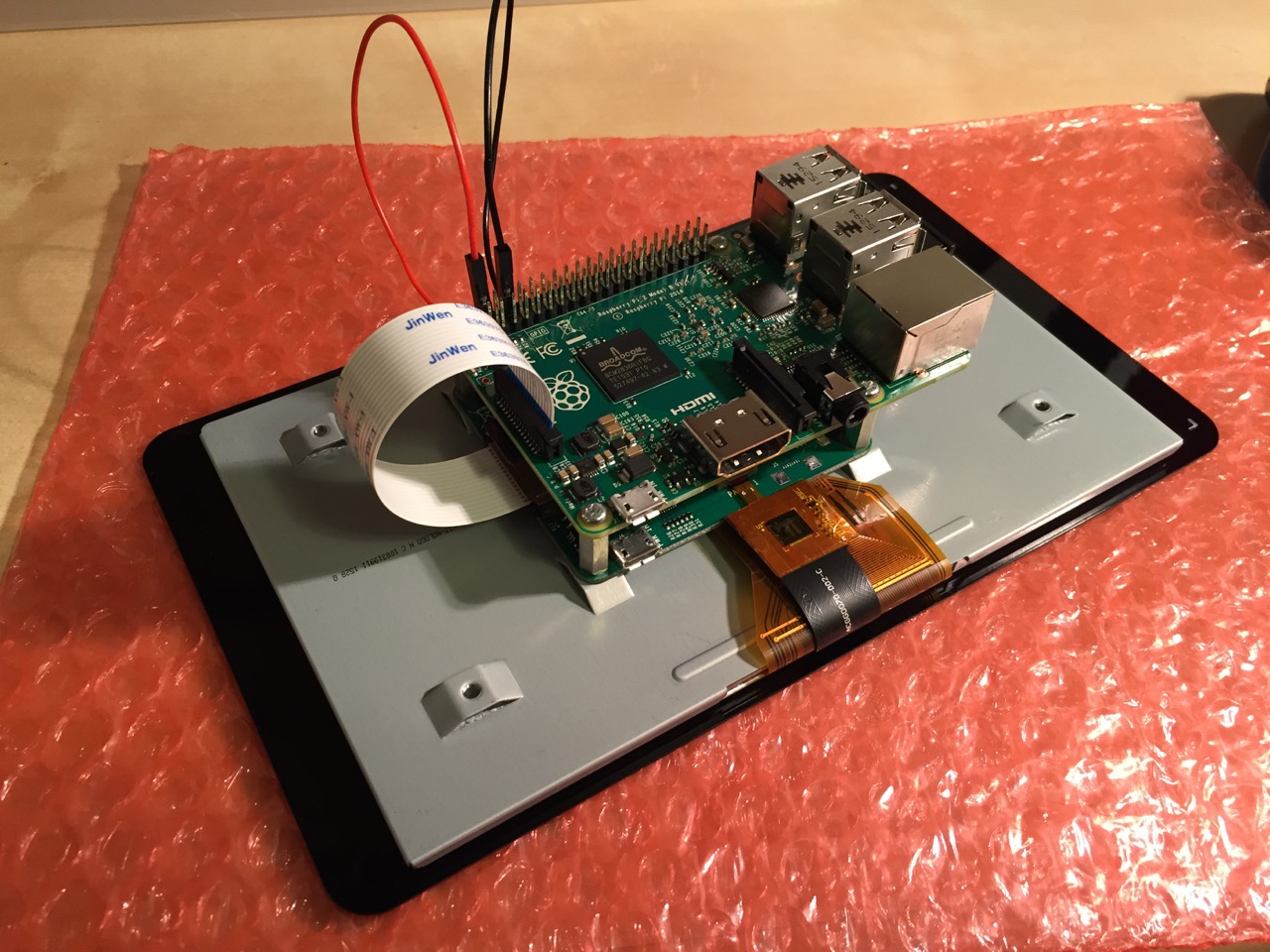
This is the rear of the 7″ Touchscreen Display assembled with the controller card and Raspberry Pi.
This is the front of the 7″ Touchscreen Display with the power leads sticking out from behind.
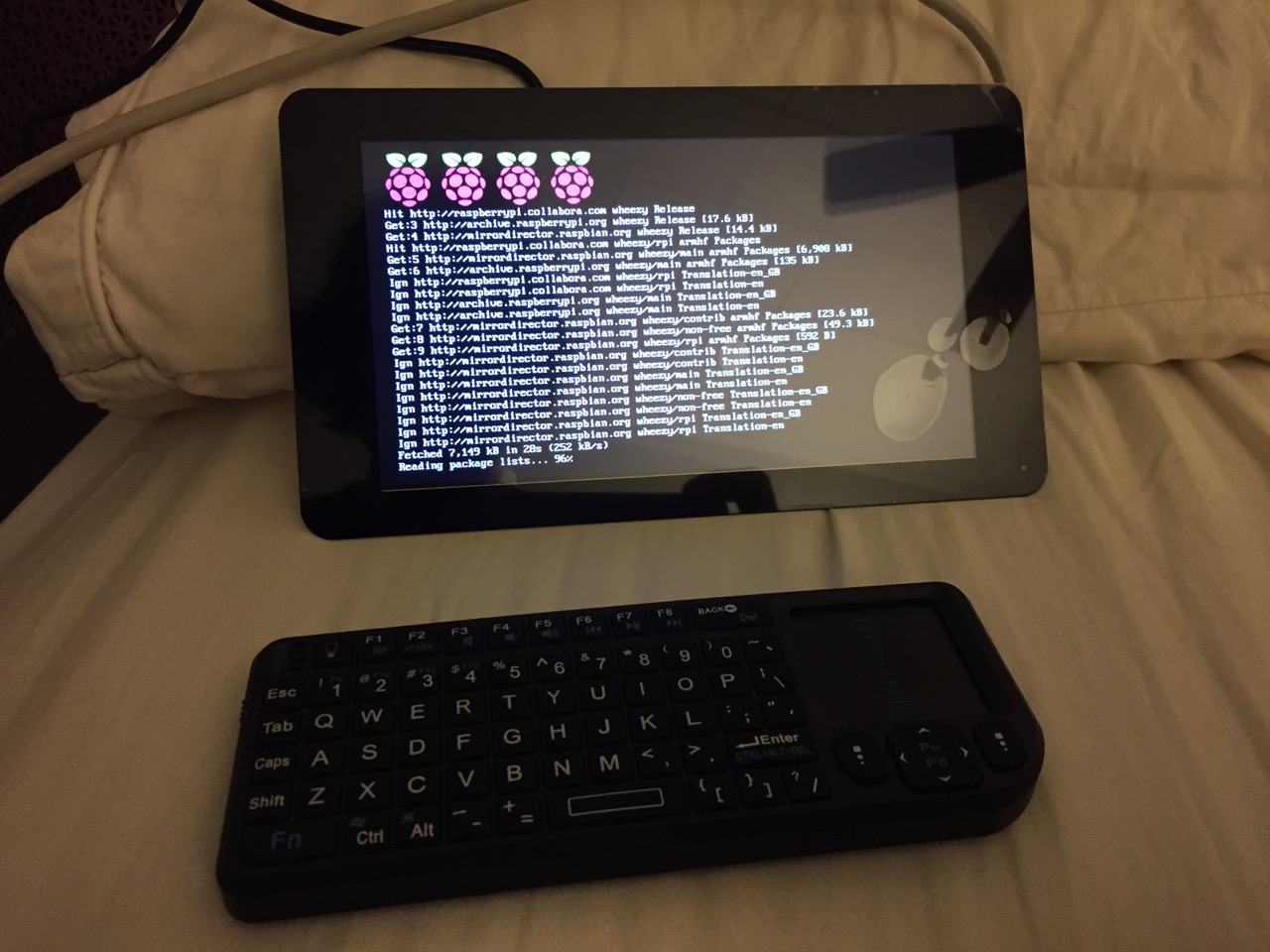
This is the Raspberry Pi powered up again with the 7″ Touchscreen Display.
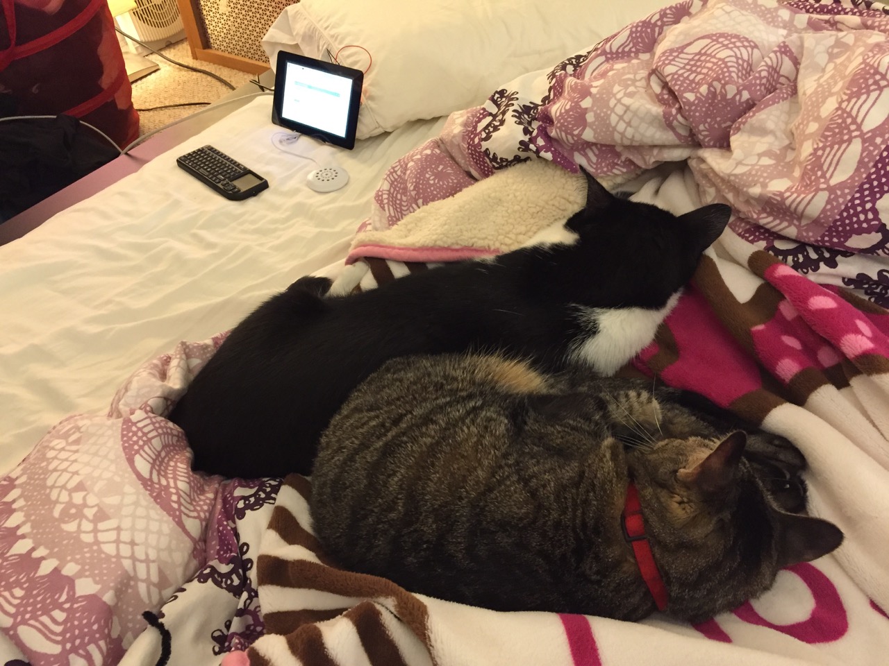
Mose and Miao had lost interest in the project by this point.
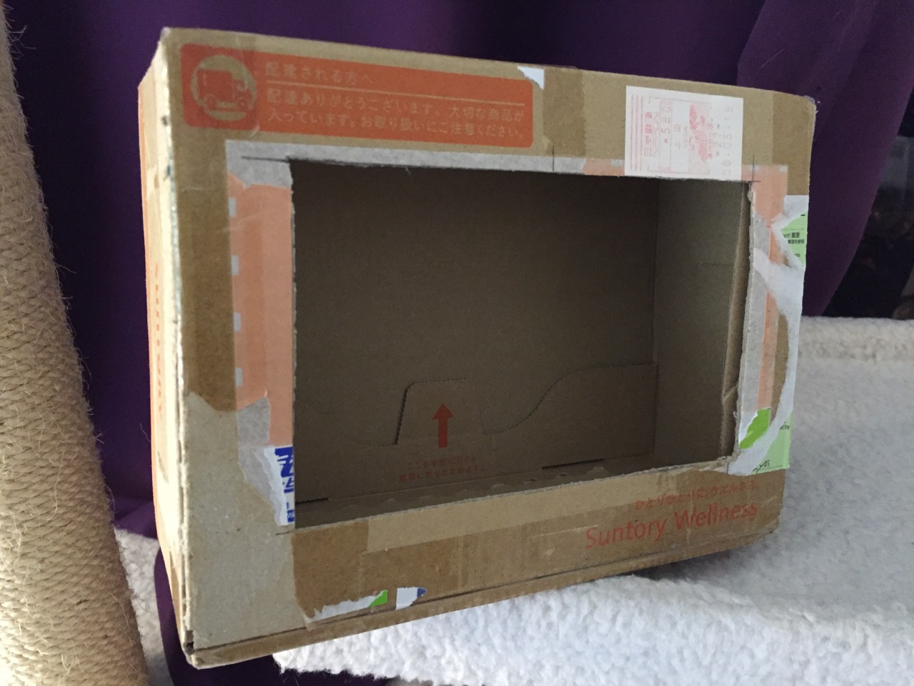
To complete the project, I cut a hole into a Suntory shipping box from Japan that is the exact same size as the 7″ Touchscreen Display box, which would work well, too. It is works well for holding up the Raspberry Pi and storing its accessories when I go between home and work.
Of course, you can use the Raspberry Pi with or without a case depending on your needs. I used the Suntory cardboard box from Japan for practical reasons (thinking: William Gibson: “the street finds its own use for things”–it’s a good size, on-hand, and looks cool) and research reasons (thinking about my work on proto-cyberpunk and the hidden nature of computing, which is an idea explored in my previous blog post about the poster that I created for the 13th annual City Tech Poster Session).
I have run the computer and touchscreen from the 5v battery that I purchased from Tinkersphere, but I get a graphics warning that the Raspberry Pi is under voltage (a rainbow pattern square persists in the upper right corner of the display whether in the CLI or xwindows). I might get a second battery to run the display alone, which would help me troubleshoot if the battery that I have now is actually outputting enough voltage and amperage needed by the Raspberry Pi alone. In the meantime, I am running everything at my desk with the 5v power adapter, which provides ample power for the Raspberry Pi and 7″ Touchscreen Display.
In the future, I would like to use the Raspberry Pi in a writing or technical communication course. There are many ways to leverage the technology: problem solving, writing about process, creating technical documents such as reports and instructions, using the Raspberry Pi as a writing/multimodal composing platform, digital storytelling with tools that come with the Raspberry Pi, and more. These ideas are built only around the Raspberry Pi and its software. A whole other universe of possibilities opens up when you begin building circuits and integrating the Raspberry Pi into a larger project.
The basic cost of entry with the platform is $30 for the Raspberry Pi 2, Model B and a few dollars for an 8GB micro SD card. If you have access to a display with HDMI, a USB keyboard and mouse, and ethernet-based Internet access, you can get started with Raspberry Pi almost immediately. For a future grant application, I am imagining a proposal to purchase the basic needed equipment to use Raspberry Pi in an existing computer lab. I can bring the kits to each class where students can use them on different assignments that meet the outcomes for that course but in an engaging and challenging way that I think they would enjoy and would be beneficial to them in ways beyond the immediate needs of the class.
On this last point, I am thinking of working with digital technology in an a way many of my students will not have had a chance to before, feeling a sense of accomplishment, learning from one another on team-based projects, experiencing a sense of discovery with a computing platform that they might not have used before, and of course, communicating through the process of discovery in different ways and to different audiences. This might be something that you’re interested in, too. Drop me a line if you are!
Bruce Sterling’s The Hacker Crackdown: Law and Disorder on the Electronic Frontier (1992) is a book that I should have read back when it was first published. In fact, I’m rather let down with myself that I did not know about this book back it was published at the same time that I was beginning high school and transitioning from an Amiga user to a PC/DOS enthusiast (if you can imagine such an animal).
Sterling’s journalistic account of the Hacker Crackdown of 1990 and its immediate aftermath is as enlightening as it is enjoyable to read. He chronicles the passage of the BellSouth E911 document, the targeting of the Legion of Doom, the criminal case against the publisher of Phrack magazine, the hentanglement of Steve Jackson Games (creator of GURPS Cyberpunk), and the launch of the Electronic Frontier Foundation (EFF).
Sterling had my attention from the get-go, but I was really jazzed when he writes about FLETC (Federal Law Enforcement Training Center) and my hometown, Brunswick, GA. He visited FLETC to speak with Carlton Fitzpatrick about computer crime.
Around that same time, I was delivering auto parts to the FLETC repair shop. I was out there at least every few days–virtually free to roam the facility in my Toyota pickup truck emblazoned with “Ellis Auto Parts” on its sides. Sterling might have been touring the facility when I was dropping off distributor points or a new starter.
Also, around that time, I was learning about DOS, Windows 3.1, and PC gaming. I had a Commodore Amiga 2000, but I was the only person besides my cousins who owned an Amiga. Of course the Amiga was a more advanced and capable computer than most IBM-compatibles, but I knew many more people with PCs and PC software. So, for a time, I indulged a hobby in PC computers (at least until I discovered the Apple Macintosh SE/30 and the computing universe that represented in Mrs. Ragland’s drafting class).
Had I read this book back then, who knows what I might have done? I imagine myself taking a detour on one of my delivery missions to the auto shop–and its interior office walls emblazoned with centerfold girls–to drop in to meet Mr. Fitzpatrick. A detour taken while driving and learning a little bit more about computers and computer security could have taken my life on its own detour from where it is now.
Had I seen computers and networks as an end in themselves–more than I did building, optimizing, and fixing them–my life would have been detoured.
As it happens, my life detoured in other, unexpected, and interesting ways. At the time, I was focused on learning about plasma physics, and in my off time, the physics of consciousness. I wound up at Georgia Tech, but I quickly learned that I was better at writing about science than doing it full time. During that time, I fell in love with science fiction–especially the New Wave and cyberpunk. I studied how to make art with new media online with HTML and Adobe Flash, and for performance with video production. I worked with James Warbington on two 48-Hour Film Festivals, and I made DVDs for Poetry at Tech (Georgia Tech).
It is own weird way, the detour comes back around so that I study the relationship between computers and the human brain, science fiction and computers, and writing pedagogy and digital media.
While things have worked out remarkably well for me despite the weird turns on my life’s road, I still consider the “what ifs,” and sometimes, I try out the “what ifs” by incorporating the “what ifs” into my daily practices. One way besides creating what I tentatively call City Tech’s Retrocomputing Lab in my humble 64 sq. ft. of office space, I decided to take my enthusiasm with computers into the Linux realm. I’ve used different distros in the past on separate partitions or in virtual machines, but this time I wanted to go all-in–perhaps after getting riled up from reading Sterling’s The Hacker Crackdown, which isn’t a story about Linux, but it is in large part about the margins and despite Linux’s successes, it is still on the margins when it comes to the personal computer desktop.
To follow through on this, I took Uber rides back and forth from Microcenter in Brooklyn (my first Uber rides–necessitated by the heat more than the distance–when the weather’s nice, I enjoy walking to Microcenter from where I live). I had discovered they had a Dell XPS 12 marked down from about $1000 to $450. I purchased one, created a backup of the Windows 8 installer (yes, it had Windows 8, not 8.1 installed), and nuked-and-paved it with Ubutu 14.04 LTS Trusty Tahr (now that I’ve fixed my cursor jumping problem initially encountered by simply turning off touchpad taps/clicks, I might venture into one of the newer versions).
Of course, I am no more a hacker than I am a neurosurgeon (this latter point, my dissertation director Mack Hassler enjoyed reminding me of despite the subject matter of my neuroscience-focused literary dissertation), but I enjoy exploring, learning, and playing. Occasionally, I do hack things together. I make things–albeit, usually simple things put together with Deckmate screws and duct tape–and I would like to make things using the computer in ways that I have not really done before. Sure, I’ve taken programming classes before, but I created what I was told to make instead of what I wanted to make. This was a lack of imagination and inspiration on my part, and I do not want to continue making that mistake. So, here we go!
This is the thirteenth post in a series that I call, “Recovered Writing.” I am going through my personal archive of undergraduate and graduate school writing, recovering those essays I consider interesting but that I am unlikely to revise for traditional publication, and posting those essays as-is on my blog in the hope of engaging others with these ideas that played a formative role in my development as a scholar and teacher. Because this and the other essays in the Recovered Writing series are posted as-is and edited only for web-readability, I hope that readers will accept them for what they are–undergraduate and graduate school essays conveying varying degrees of argumentation, rigor, idea development, and research. Furthermore, I dislike the idea of these essays languishing in a digital tomb, so I offer them here to excite your curiosity and encourage your conversation.
In the next few Recovered Writing posts, I will present my major assignments from Professor Kenneth J. Knoespel’s LCC 3314 Technologies of Representation class at Georgia Tech. LCC 3314 is taught in many different ways by the faculty of the Georgia Tech’s School of Literature, Media, and Communication, but I consider myself fortunate to have experienced Professor Knoespel’s approach to the course during the last phase of my undergraduate tenure. The ideas that we discussed in his class continue to inform my professional and personal thinking. Also, I found Professor Knoespel a great ally, who helped me along my path to graduation with side projects and independent studies.
This is another example of a WOVEN multimodal essay assignment. In it, I used WVE/written, visual, electronic modes to discuss a specific technology. These essays (focused on past, present, and future technologies) gave me a chance to use technology to explore the meaning behind and impact of technologies. The next essay will focus on a future technology of my own design.
In this essay assignment, we were tasked with exploring an imagined future technology. At the time, I was fascinated with wearable computing. However, I only knew about it from my reading in magazines and online. I could not afford a 2004-era wearable computing rig, so I thought about how to improve on an idea of wearable computing for everyone. If only I had made a few more connections–namely touch and the phone.
Nevertheless, I had a lot of fun designing the PCD and writing this essay.
Jason W. Ellis
Professor Kenneth J. Knoespel
LCC3314 – Technologies of Representation
November 18, 2004
Artifact of the Future – Personal Computing Device
Personal Computing Device – PCD (Drawing by Jason Ellis)
The Artifact
The Personal Computing Device (PCD) is an inexpensive and portable computer that can interface with many different input/output (I/O) components. It is a one-piece solution to the ubiquity of computing and information storage in the future. Its plain exterior hides the fact that this artifact is a powerful computing platform that transforms “dummy terminals” into points of access where one may access their own computer that is small enough to fit in a shirt pocket.
Description
The device measures 3″ wide by 4″ tall by 3/4″ thick. On one of the long sides there is a small 1/4″ notch. This notch matches with a similar notch on the interface port of wearable computer networks, computing stations, and entertainment systems. The notch allows user to insert the PCD in only one orientation. This protects the PCD and the interface port it is being plugged into. The PCD is housed in a thin aluminum shell. As the PCD does computing work, its circuits emit heat which needs to be removed from the system. Because of the very small (< 90nm) circuit manufacturing process, the PCD uses very little power which translates to it emitting less heat than today’s Pentium 4 or Athlon64 processors. Aluminum is an excellent choice for its metal housing because it is thermally conductive (removes heat), it is lightweight, and it is inexpensive.
Dimensional view of PCD (Drawing by Jason Ellis)
There are no switches or indicators on the PCD. It has only one interface port as pictured in the top-left of the drawing above. This interface makes the PCD unique. This standardized interface allows the PCD to be used on any computing system that is designed for the PCD. Computer hardware, wearable computer networks, and home entertainment systems are “dummy terminals” which rely on the PCD to be the “brains.”
The PCD is a full featured computer. It processes data, runs programs, and stores data on built-in solid-state memory. Engineers were able to build a complete “computer on a chip” using new silicon circuitry layering techniques. The result of this is the Layered Computing System as drawn in the internal schematic of the PCD (below). Reducing the number of chips needed for a computing application has been a long-standing goal of electrical and computer engineering. Steven Wozniak at Apple Computer was able to design elegant layouts for the original Apple I, and later, the Apple II. He designed custom chips that brought the functions of several chips into a single chip. AMD is continuing the trend today after integrating the CPU memory controller onto the new Athlon64 processor. NVIDIA introduced the nForce3 250 GB chipset which integrated the system controller chip, sound, LAN (networking), and firewall all onto one chip.
Internal layout of the PCD (Drawing by Jason Ellis)
The solid-state memory is similar to today’s flash memory (e.g., USB Flash Drives or compact flash digital camera memory). The difference lies in the density of the memory on the PCD. Layering techniques are used in building the solid-state memory so that it is very dense (more data storage per unit area than today’s flash memory). Typical PCD solid-state memory storage is 120 GB (gigabytes). The PCD’s large memory area has no moving parts because it is made out of solid-state memory. Traditionally, computers need a hard drive to store large amounts of information for random access. Hard drives are a magnetic storage that depends on round platters rotating at high speed while a small arm moves across the platters reading and writing information. Flash memory does not need to spin or have a moving arm. Data is accessed, written, and erased electronically.
The PCD has a built-in battery for mobile use. When the PCD is plugged into a wall-powered device such as a computer terminal or entertainment system, it runs off power supplied by the device it is plugged into and its battery will recharge.
Social Significance
The introduction of the PCD revolutionizes personal computing. The PCD empowers users to choose the way in which they interface with computers, networks, and data. Computer displays, input/output, and networks have become abstracted from the PCD. A user chooses the operating system (the latest Linux distribution, Windows, or Mac OS X) and the programs (e.g., Office, Appleworks, iTunes) for his or her own PCD. That person uses only their own PCD so that it is customized in the way that they see fit and they will develop an awareness of its quirks and abilities in the same way that a person learns so much about his or her own car.
The “faces” of computers (i.e., monitors, keyboards, mice, trackballs, and printers) are abstracted away from the “heart” of the computer. The PCD is the heart because it processes data through it (input/output) much like the heart muscle moves blood through itself. A PCD also acts as a brain because it stores information and it can computationally work on the stored data. The traditional implements of computer use are transformed into dummy terminals (i.e., they possess no computational or data storage ability). Each of these devices have an interface port that one plugs in their personalized PCD. The PCD then becomes the heart and brain of that device and it allows the user to interface with networks, view graphics on monitors, or print out papers.
Computer Terminal and Entertainment Systems with PCD Interfaces (Drawing by Jason Ellis)
Both the PCD and the dummy terminals are a standardized computing platform. Consumer demand, market forces, and entrepreneurial insight led to the evolution that culminated with the PCD as the end product. Consumers were overburdened with desktop computers, laptop computers, and computer labs. Every computer one might encounter could have a very different operating system or set of software tools. The data storage on one computer would differ from the next. A new standard was desired to allow a person to choose their own computing path that would be accessible at any place that they might be in need of using a computer.
Computer manufacturer businesses saw ever declining profits as computers were becoming more and more mass-produced. Additionally, no one company built all of the parts that went into a computer so profit was lost elsewhere as parts were purchased to build a complete computer for sale.
New integrated circuit manufacturing techniques allowed for greater densities of transistors and memory storage. These manufacturing techniques also allowed for lower power consumption and thus reduced heat from operation (which was a long-standing problem with computers).
With the consumer, desire for something new and innovative coupled with a new way of building computer components led to the founding of a new computer design consortium. Hardware and software manufacturers came together to design a computing platform that would fulfill the needs of consumers as well as improve failing profits. The PCD design consortium included computer and software businesses, professional organizations, and consumer/enthusiast groups.
The PCD almost didn’t see the light of day because of influence from large lobbying groups in Washington. This involved copyright groups such as the Recording Industry Association of America (RIAA) and the Motion Picture Association of America (MPAA). These groups decried the potential copyright violations possible with the PCD. Epithets, curses, and bitching issued from the RIAA and MPAA lobbyists’ mouths. Consumer outrage over these large business groups attempting to throw their weight around caused a surge of grassroots political involvement that unseated some Congressional members and scared the rest into line. The public wanted to see what would come out of the PCD Design Consortium before judgment was passed on its useful and legal purposes.
With the legal hurdles temporarily under control, the PCD was released to the public. New and inventive uses were immediately made of the PCD. One of the first innovations involved the Wearable Computer Network. Wearable computing was a long researched phenomenon at the Wearable Computing Lab at MIT and Georgia Tech’s Contextual Computing Group. The two factors holding back wide adaptation of wearable computing were the cost of the mobile computing unit and the mobile computing unit’s singular purpose. These two factors were eliminated by the PCD because it was cheap and it could be removed from the wearable computing network and used in other computing situations (e.g., at a desktop terminal or in an entertainment system).
Wearable Computing Network with Integrated PCD Interface Pocket (Drawing by Jason Ellis)
Entertainment systems and desktop terminals became popular receptacles for the PCD. Music and movies purchased over the Internet could be transferred to the PCD and then watched on a home entertainment system that had a PCD interface port. Desktop terminals and laptop terminals also began to come with PCD interface ports so that a computer user could use their PCD at home or on the go, but still be able to use their PCD in other situations such as at a work terminal. Being able to carry a PCD between work and home allowed for easier telecommuting because all of a person’s files were immediately available. There was no more tracking down which computer had downloaded an email, because a person’s email traveled with that person on his or her PCD. Easier teleworking helped the environment in metropolitan areas because more people could do their work from home without needing to drive their fossil fuel consuming cars down the highway.
Instant computing access meant that PCD users were able to expand the possibilities of the human-computer dynamic. There was more Internet use and that use was more often on the go. As people began donning wearable computing networks for their PCD, they would chat with friends while riding a commuter train or they would spend more time getting informed about what was going on in the world with NPR’s online broadcasts or with the BBCNews’ website. Social networks like Orkut and Friendster received even more users as friends began inviting friends who may have just got online (with a mobile setup) with their new PCD.
As more computer, clothing, and HDTV terminals began to support the PCD, more jobs were created, more units were sold, more raw materials were consumed, more shipping was taking place, more engineering and design was going on, and new business models were being created. The web of connections built upon itself so that more connections were made between industries and businesses. The popularity of the PCD boosted tangential industries involved in building components that went into the PCDs as well as entertainment services. Aluminum and silicon processing, chip manufacturing, battery production and innovation (for longer battery life), new networking technologies to take advantage of the greater number of computing users who purchase PCDs, and PCD interface devices (such as HDTVs and wearable computing networks) all ramped up production as demand for the PCD rose. New services popped up such as computer terminal rental and new entertainment services that would allow customers to purchase copy-protected versions of music and movies that could easily be transported for enjoyment wherever the user took his or her PCD. Some entertainment companies held out too long while others reaped rewards for modifying their business models to take advantage of this new (and popular) technology.
Choice is the driving factor behind the PCD’s success. Wrapped in the PCD’s small form is the choice of human-computer interaction, choice of where to use a PCD, and choice of data (visual and auditory) to be accessed with a PCD. These choices are made available by the choices made by many people such as consumers, industrialists, and entertainment antagonists. Those who embraced the PCD and found ways of interfacing with it (literally and figuratively) succeeded while those that did not were left by the wayside.
There are a number of useful guides to installing Mac OS X and Ubuntu in a dual boot configuration on Macintosh hardware such as James Jesudason’s guide here or Alex Victor Chan’s guide here. However, I ran into a problem with Mac OS X 10.8 Mountain Lion not waking from sleep due to using the rEFInd bootloader (more information about this problem documented on this thread).
The following is the process that I used for successfully having Mac OS X and Ubuntu play well together on my MacBook Pro Retina (MacBookPro10,1) (15.4″/2.6 Quad-core i7/8GB/512 GB SSD)
Using a Mac OS X 10.8 bootable USB flash drive (create your own by following the DIY instructions here), partition your drive into two equal partitions with Disk Utility. Format the first partition as Mac OS Extended (Journaled) and the second as free space.
Install Mac OS X on the Mac OS Extended (Journaled) partition.
Boot into Mac OS X, download the rEFIt bootloader, and install it in Mac OS X. Reboot your Mac twice and you should see the rEFIt bootloader screen appear after the second reboot. It will have your Mac OS X installation highlighted. Press Enter to boot.
Create a bootable USB Ubuntu disk with this guide for Mac OS X. It will involve downloading the Ubuntu 13.04 ISO image, converting it for Mac OS X, and using terminal commands to write the converted image to your USB drive. When it is all done, Mac OS X will not recognize the disk and ask you to initialize it. Choose “Ignore.”
Reboot your MacBook Pro with the Ubuntu USB drive inserted. rEFIt will give you the option to boot Mac OS X (Apple icon) or Ubuntu (this might appear as two separate icons depicting four squares in a diamond configuration). Choose the first Ubuntu icon with the arrow keys on the keyboard, press Enter.
Next, GRUB, another bootloader, will appear as white text over a black background (like DOS) and give you options to Try Ubuntu or Install Ubuntu. Unlike the other guides, I suggest selecting Install Ubuntu from this menu.
The Ubuntu installer will guide you through the setup process. The only setting that you have to select is “Install alongside Mac OS X.” The Ubuntu installer will automatically find the free space partition that you created earlier, partition it in a way that Ubuntu anticipates, and install Ubuntu and its included software.
At the end of the installation, it will return to a text-based screen and prompt you to remove the installation USB drive and press a key to reboot.
After rebooting, rEFIt should show your Mac OS X installation (Apple logo) and Ubuntu represented by three stacked, colorful boxes (subtitled: EFI\ubuntu\grubx64.efi from EFI). Select the Ubuntu installation with the arrow keys and press Enter. GRUB will appear, select Ubuntu and hit Enter.
The Ubuntu desktop should load very quickly, but it will appear very tiny at the native resolution of the MacBook Pro Retina’s 2880 x 1800 resolution. To adjust the resolution, click on the Gear/Wrench icon in the launch bar on the left to enter system settings. Click on Displays, choose a new resolution (I use 1680 x 1050), click Apply, and Confirm.
The status bar at the top of the screen will show familiar icons for Bluetooth, WiFi, sound, and system/shut down (If Ubuntu does not automatically detect your WiFi card, you can download this package and its three dependencies from within Mac OS X, put them on a USB drive, reboot into Ubuntu, install each from terminal using the “sudo dpkg -i filename.deb” command for each–though, leave the Broadcom deb package for last. I downloaded the nightly build of 13.04, which I believe has this package on the installation disk.).
To switch between installations, simply reboot the one that you are in and select the system that you want to run from rEFIt.
Apple’s friendly byte.
Now, you can run Ubuntu or Mac OS X on your MacBook Pro. Here are some important things that you should do in Ubuntu after installation.
Also, it is possible to take GRUB out of the equation by installing Ubuntu with the “ubiquity -b” command from within the Live CD version of Ubuntu and configuring rEFInd or rEFIt, but I had trouble getting Ubuntu to boot following Jesudason’s guide for rEFInd (the fault is likely with what I did and not his thorough instructions). I can live with GRUB if it means that I can get my work done in these two computing environments on my MacBook Pro.
If there is interest among Brittain Fellows, I can incorporate this into the series of DevLab Workshops that I am planning for the upcoming year.