When Y and I lived in Atlanta, our house had a downstairs bedroom that we used for an office. However, it was an odd room. The kitchen and downstairs bathroom had tiled floors, and the rest of the downstairs–dining room, living room, and den–had hardwood floors. That downstairs bedroom had medium pile carpet. When our friend Masaya asked if he could visit us, we thought it was a good opportunity to refinish the downstairs bedroom as a guest room with hardwood floors. Here’s how we refinished its floor to match the stain of the rest of the downstairs.
First, I pulled up the carpet in the closet and a corner of the room to verify that it was the same kind of oak flooring as the rest of the downstairs. Having verified this, I began cutting and rolling the carpet and padding.
The padding had been glued down–thankfully not over the entire floor–but enough that I had to scrape some of it and the glue off the wood flooring using a paint scraper. However, I went slow and carefully to make sure that I didn’t gouge the wood with the tool. Whatever I didn’t get up, I knew that I could sand down eventually.
Then, I used a hammer to pull up the carpet tack strips around the edges of the room and vacuumed the floor clean.
For the next step, I went to the local Home Depot Rental Office to rent a stand-up belt sander for floors. This thing weighed about 100 pounds. It’s weight combined with a handle operated mechanism to engage the sanding belt against the floor and pull it forward made quick work of sanding the floor and removing all old paint, glue, and stains. As the wood wasn’t in too bad of shape, I used a fine grit sandpaper. Also note that when you use a floor sander like this, you want to move in the direction of the boards and give each pass a little overlap for an even finish across the whole floor. Also, you can see that I have the windows open. Even though the sander has a bag to catch the sawdust, it can’t catch it all. Open your windows and cover outlets and air returns to keep that dust from getting into places it shouldn’t be.
Halfway through, I changed out the belt for a fresh one. This probably wasn’t necessary, but I might have noticed some change in the sanded floor’s finish by this point in the project.
After using the belt sander over the whole floor, I saw some spots that needed additional work. When I did these spots, I went over the entire run as just using it in one spot might leave a dip in the floor. As I worked, I used the shop vac to keep the floor as clean as possible from the extra sawdust produced by the sander. And, around the edges of the room and inside the edges of the closets, we used a handheld orbital sander and sanding blocks to sand the 2″ or so on all sides that the belt sander was unable to reach due to its design.
After returning the belt sander to Home Depot, we cleaned the floor again and applied water to the wood with cloths to “pop the grain.” This makes the wood more receptive to the stain so less is needed to achieve the results that you want.
Before, we had taken photos of the existing hardwood floors in the house using natural light to capture the best image of the stain. We took this to Home Depot and matched it to a water-based stain and polyurethane combo so that we could finish the floor as soon as possible and give it time to cure and air out before moving furniture back in anticipation of our friend’s arrival.
With the wood damp, I stirred the stain/poly combo according to the instructions on the can and poured out some into a paint tray. Then, I dipped a foam paint/finish applicator into the stain/poly and gently worked it into the wood in the direction of the boards.
Once completed, give the floor enough time to air out and cure before moving things back in. If you don’t have to walk on it, just wait until its met the cure time as this will give you the strongest possible finish.
I didn’t want to pull up the baseboard, so I went back after the floor’s finish had cured and repainted the baseboard (putting down plastic, taping the edge, and putting enough coats to hide the stain that hit it). In hindsight, I should have taped the baseboard to protect it. However, the best option is to pull up the baseboard and reinstall after refinishing the floor.
We were very happy with the results. It was ready for our friend’s visit and we used it as an office again after he returned to Japan.
I like Syncthing, the continuous file synchronization program. Syncthing helps me pickup and continue my work regardless of the device I happen to be using, because it synchronizes my files across all devices. Think Dropbox but on my own hardware.
Also, I like tiny, low-power computers, like the Raspberry Pi 2. The Raspberry Pi and other lightweight computers demonstrate how even small computers are powerful enough for servers and desktop computing.
When Dropbox became more bloated with the new app design and refusing to offer a lower cost tier for those of us with modestly lower file synchronization needs, I began using Syncthing to create a folder of files synchronized between my desktop computer (at home) and my Surface Go (laptop used at work). I’ve been wanting to add a third node in my personal cloud storage solution, in part as an exercise in Linux and tiny computing and in part as another safe repository of my files. So, it made sense to combine my use of Syncthing with my enthusiasm for tiny computing by adding a third node to my Syncthing setup with a $10 Raspberry Pi Zero W (RPi0).
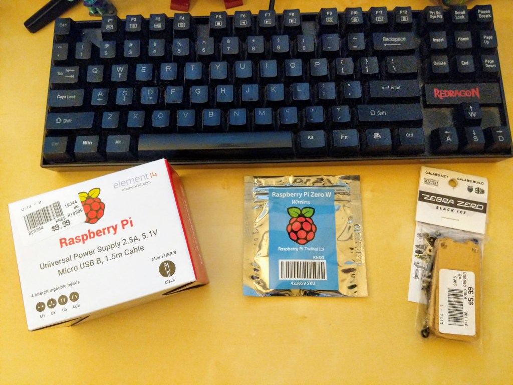
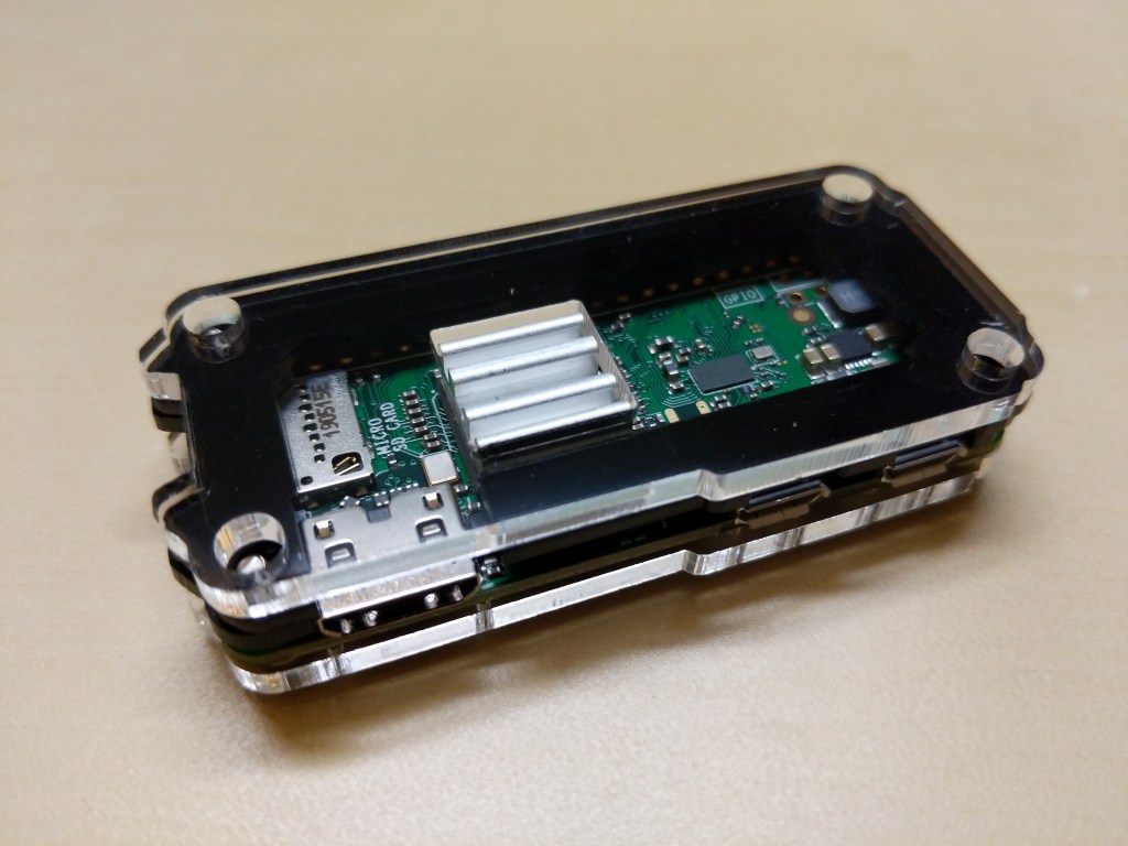
Raspberry Pi Micro USB Power Supply, Raspberry Pi Zero W, and C4 Labs Zebra Zero Black Ice Case
I picked up a RPi0 version 1.1, a C4 Labs Zebra Zero Black Ice Case with heatsink from Microcenter using their curbside pickup, which cost about $26 total.
I setup the RPi0 as a headless computer, meaning that it doesn’t have a monitor or keyboard attached. I will configure and control it remotely over my LAN.
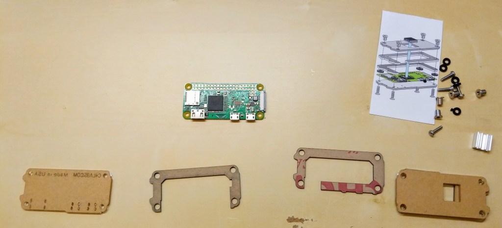
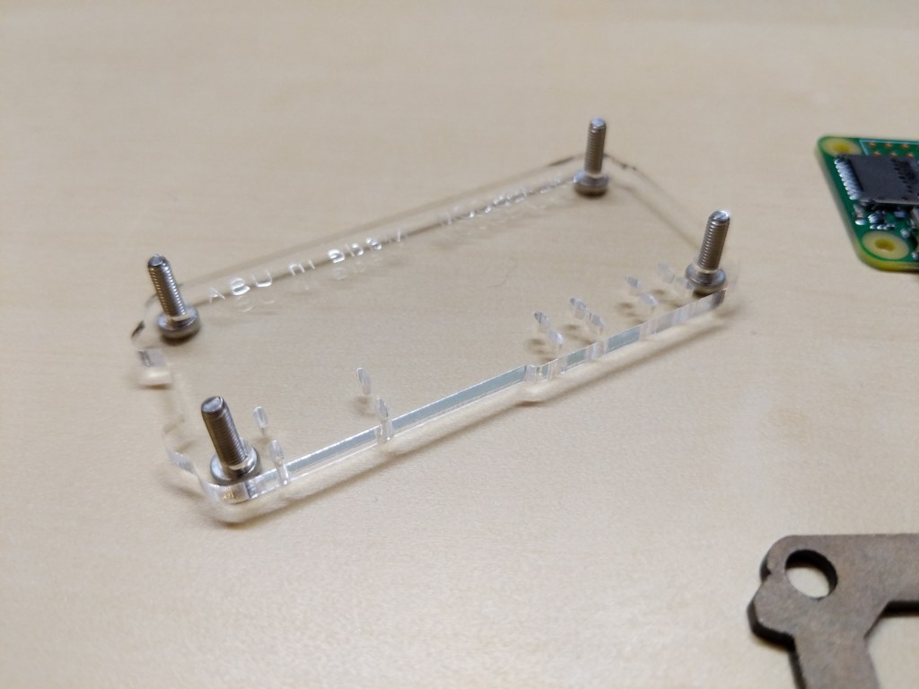
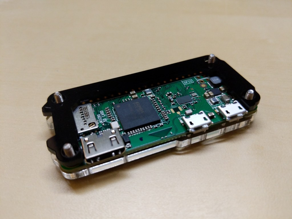
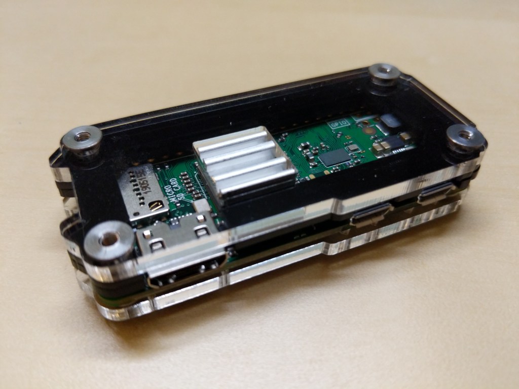
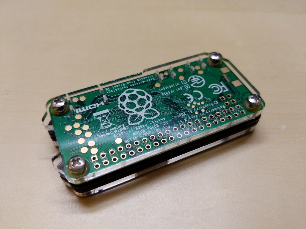
Before turning to the software and preparing the microSD card for the RPi, I assembled the case and installed the heatsink on the CPU. A case for the RPi0 wasn’t necessary, but I thought it prudent to get one for two reasons: 1) I have a cat and a small thing with a wire sticking out might be enticing, and 2) I plan to leave it on all the time, so a heatsink like the one included in this case kit will help dissipate heat produced by the RPi0’s CPU.
Assembling the Raspberry Pi Zero W in a C4 Labs Zebra Black Ice Case with Heatsink
Before powering up the RPi0, I downloaded Raspbian Lite (a lean version of the Linux-based Raspbian OS for the RPi), balena Etcher (to burn the installer image to my microSD card), PuTTY (to SSH into the RPi0 to configure, administer, and install software), and Apple’s Bonjour network printer software (to easily connect to the .local hostname of the RPi0).
Since I installed Apple’s Bonjour software as part of Mitch Allen’s instructions above, I was able to easily connect to the RPi0’s Syncthing web admin page by going to “raspberrypi.local:8384” on my desktop’s web browser.
Before setting up Syncthing to sync files, I wanted to lockdown the web admin page by going to Actions > Settings > GUI where I checked “Use HTTPS for GUI” and added a “GUI Authentication User” and “GUI Authentication Password”.
As a test, I rebooted the RPi0 and confirmed that Syncthing launched automatically at bootup and confirmed that authentication was required to access the web admin page remotely.
Also, I made sure that I had Syncthing running on the desktop computer and the RPi0. Due to some initial problems with syncing, I unlinked my desktop and Surface Go from syncing, and moved the files and folders out of my default sync folder so that the sync folder is empty to begin with.
Then, I added a remote device to Syncthing on my desktop PC and on the RPi0 (both installations of Syncthing have to have the other device added).
On each Syncthing web admin page click “Add Remote Device” to add the other computers that you want to sync
First, on each computer (in my case, the desktop PC and the RPi0), click “Add Remote Device” on the Syncthing web admin page.
Enter the Device ID generated by Syncthing on the other computer. On my local network, it auto-suggested the ID of the desktop PC on the RPi0 and vice versa.
Second, on the “Add Device” screen that appears, type in the Device ID of the other computer. In my case, Syncthing auto-suggested the Device ID of the desktop PC when I was configuring the RPi0 and vice versa since these devices are on the same local area network.
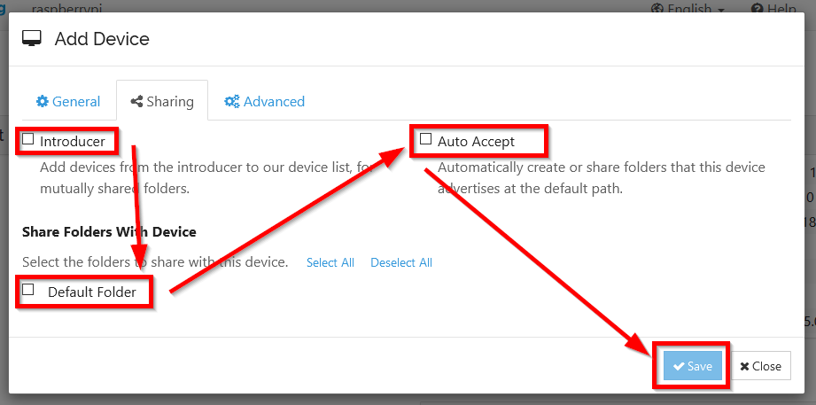
On the Sharing tab, check all three boxes
Third, click on the “Sharing” tab on the “Add Device” screen, and check all three boxes: Introducer tells connected devices to add devices from the other synced devices, Default Folder is what folder is being shared, and Auto Accept will automatically include new folders created or shared within the default shared path. Finally, click “Save.”
After adding each other device on each Syncthing installation, they should begin syncing the default folder. I added one file back on my desktop PC to test this. After that file synced on both devices, I added my files back and they began syncing with the RPi0.
The final step in my setup was to add the Surface Go as another remote device. After starting Syncthing on the Surface Go, I added it to the desktop PC and I added the desktop PC to the Surface Go’s Syncthing configuration. While the Surface Go began copying files, the RPi0 added the Surface Go as a remote device automatically. Now, all three devices sync my files.
A better configuration would be to have the RPi0 off-site so that my files would be protected from burglary or fire. Therefore, I wouldn’t recommend Syncthing as a foolproof backup solution that gives you the same sense of security as off-site storage unless you can arrange to have your files off-site (then, I would recommend going further than what I did and have your RPi0’s drive encrypted to protect your files should the off-site device be compromised).
For my purposes, using Syncthing on two work-focused devices and one tiny RPi0 computer server gives me some peace of mind through an additional layer of redundancy.
Now, I want to explore what else I can have this RPi0 do as a headless server!
Due to COVID-19, City Tech (and all of CUNY) shifted its in-person classes to online, distance learning instruction. In this post, I reflect on my current class’s transition to distance learning, show how I have configured my office and computer for screencasting and video conferencing, describe some software and services that support distance learning, and give instructions for uploading a video to YouTube.
My Transition to Distance Learning
For my current Science Fiction (ENG2420) class, this was not too much of a disruption, because I was already leveraging online technologies to support student learning and course material accessibility. I designed the course as a zero textbook cost class, meaning I find resources that I can make available to students via PDFs and handouts, and choose readings that are available freely online, such as the unparalleled Archive.org.
Also, I redesigned some of the course assignments to emphasize the importance of note taking by teaching good note taking practices and evaluating students on the quality of their notes. To support this, I recorded each lecture during our earlier in-person classes and posted them on YouTube after class ended, so that students could use the videos to fill in gaps in their notes and allow those students who missed a class to make their own notes based on the video lectures.
I collect student work via email and on OpenLab, “an open-source, digital platform designed to support teaching and learning at City Tech (New York City College of Technology), and to promote student and faculty engagement in the intellectual and social life of the college community.” I joined the OpenLab team as a co-director of the project this year, but I have been using OpenLab in all of my classes since joining City Tech in 2014.
Now with classes meeting asynchronously online, I have tweaked assignments and the schedule to accommodate students accessing materials and completing their assignments. I hold office hours once a week at a regularly scheduled time via Google Hangouts, and I can hold private office hours by appointment with students. I use email to respond to questions and concerns on a daily basis.
Now that I have reconfigured a space in my apartment to support my class and the many other online meeting responsibilities that I have with OpenLab and other projects, I wanted to share some tips and ideas to help others transitioning to facilitating their classes with distance learning.
Office Configuration
I know how easily distracted I am by busy backgrounds, I wanted to provide as neutral a space for my lectures and online meetings. To this end, I appropriated my apartment’s closet as a distance learning and video conferencing studio.
I positioned the Logitech C615 webcam so that I am centered in the frame when video conferencing or recording myself lecture. Above the camera, I positioned a white light to illuminate my face.
I arranged the desk so that my back would be against a solid white wall as pictured above looking from behind my monitor towards where I would be sitting facing the monitor and webcam.
Notice that I taped a small piece of cardboard above the webcam. This blocks glare on the camera lens from the light above that illuminates my face. I was careful to cut and position it so that it is out of frame of the camera lens. Depending on your webcam, be careful not to cover the microphone if you build a similar lens shade.
To the side of my desk, I have a larger lamp that points against the wall and behind me. This reduces my shadow from the desk lamp in front of me.
The end result looks like this:
Software and Online Services for Distance Learning
As mentioned above, I use email and the OpenLab for interacting with students, disseminating materials, and collecting student work. And, I am using Google Hangouts for regular office hours since it is a far easier lift for students than official CUNY supported video platforms like Skype and WebEx.
To create my class lectures, I do the following things.
First, I create a presentation slide deck using Slides in Google Docs.
While presenting my slides in full screen mode, I use OBS Studio, a “free and open source software for video recording and live streaming” that supports Windows, Mac, and Linux, to record a video of my desktop (the Slides presentation) and my webcam video and audio in a smaller picture-in-picture that positioned in the lower right corner of the screen, which produces a video like my recent lecture embedded below.
Before I can post the video to YouTube, I like to edit it (though, editing isn’t absolutely necessary). I like to use Shotcut, a “a free, open source, cross-platform video editor.” After trimming the video, I then upload it to YouTube, get the video’s sharable link, and embed the video with the link in my class’ OpenLab site.
OBS Studio and Shotcut have steep learning curves, but each have extensive online documentation and there are communities of users online who share tips and advice about how to setup and use these powerful tools.
In some cases, you might not even need a computer. iPhones with iOS and Android phones can use video recording software that’s built-in or with an app to record and edit video, and there’s a YouTube app for both platforms that you can use for uploading the resulting video.
In the next section, I will show you step-by-step instructions for uploading a video made on a computer to YouTube.
Uploading a Video to YouTube
Once you have a video ready to share with students, the following step-by-step guide for uploading your video to YouTube shows you how to upload and share a link to your video.
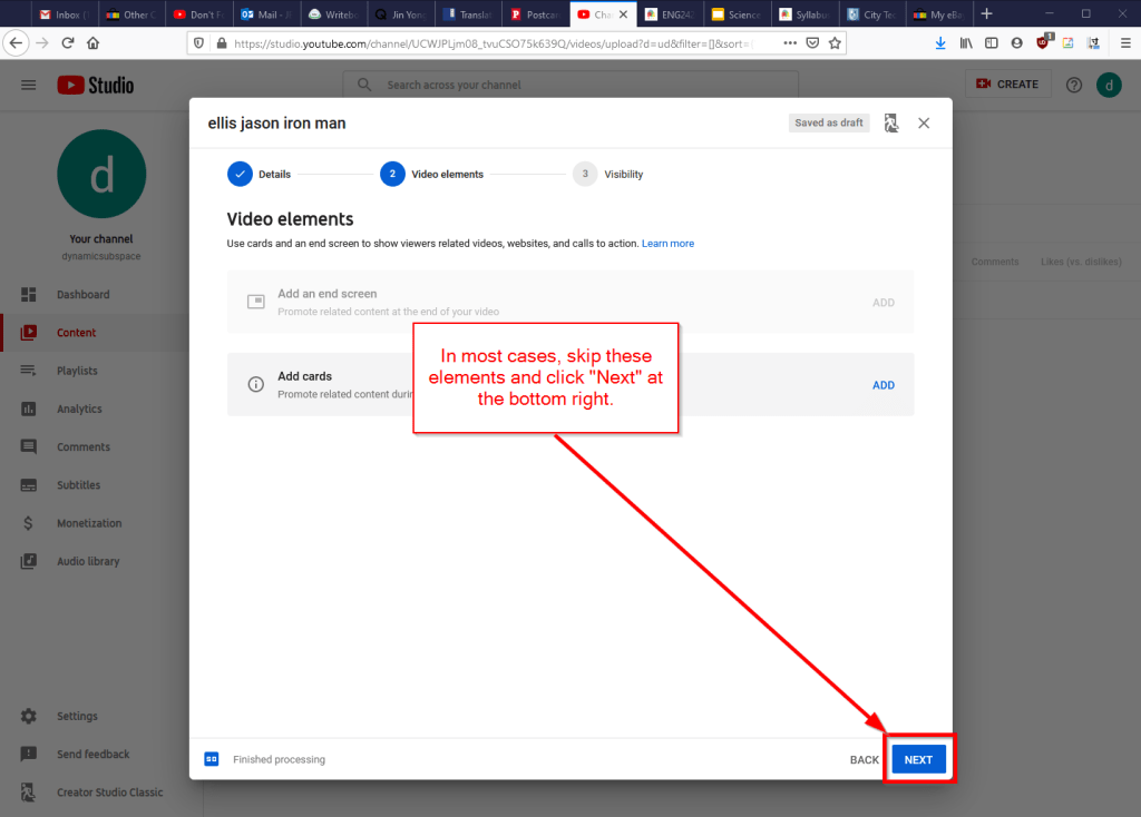
First, navigate to YouTube.com and login to your account. Then, click on the camera icon in the upper right corner and then click “Upload Video.”
Second, drag-and-drop your video from your computer into the center of the window that opens, or click on “Select File” to navigate to and select your video file on your computer.
Third, while your video is uploading and processing (updates are shown along the bottom edge of this window shown above), fill out the Title and Description boxes and choose a thumbnail for how the video will initially display before the play button is pressed. Then, scroll down the window.
To comply with the COPPA law, select if your video is for kids or not. Then, click Next in the lower right hand corner.
Fourth, you can skip the options on the Video Elements screen and click Next in the lower right corner.
Fifth, select the Visibility option for your video. The most versatile choices are Public (this is what I choose) and Unlisted. In these cases, you will have a sharable video link that you can send via email or easily embed in a webpage. Private is also an option, but you have to choose who is permitted to see the video, which requires students having a Google account and you knowing those accounts to grant permission to each one. After making your selection, click Publish in the lower right corner.
Finally, highlight and copy the video link on the resulting screen, or click on the copy icon on the right to automatically copy the video link to the Clipboard. Click “Close” on the lower right to return to your list of videos on YouTube. With the link on your Clipboard, you can go to email, OpenLab, or another platform to paste and share the video link with your students.
On OpenLab and WordPress-based sites, pasting the link into a post or page will automatically embed the video so that students can simply navigate to your class site and watch the video on the class site instead of going over to YouTube as an additional step.
If you’re working on transitioning your classes to distance learning, it’s okay to feel overwhelmed and frustrated like Miao Miao below. Just don’t give up. We’re doing good work for our students, and it takes time to think through and implement distance learning. Also, it’s okay to let your students know that this is a work-in-progress and things might change based on what works and what doesn’t.
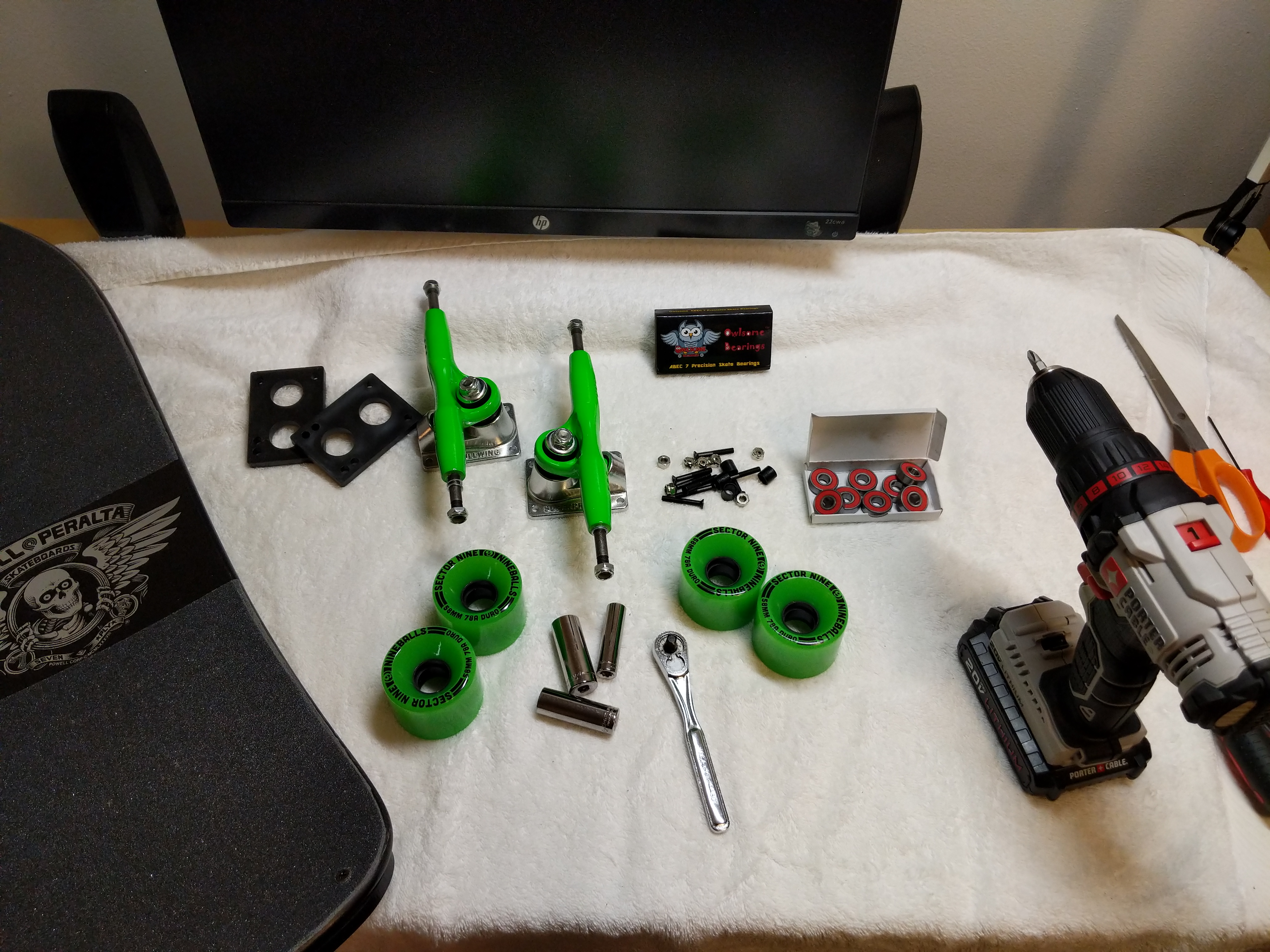
My Mike McGill Pro Model “Skull and Snake” Re-Issue Series 5 by Powell-Peralta, Complete with Gullwing Pro III Trucks and Sector Nine Nineballs Wheels.
This is a long read that combines autobiography, nostalgia, memory, and instructions. Visitors here might find it interesting and informative. My students might use it as a model for some of their own multimodal writing about memory, processes, instructions, and reflection.
While it has been over 25 years since I last rode a skateboard with my hometown friends, I recently felt drawn to the 7-ply deck once again and decided to assemble a board similar to my second skateboard–a 1990 Powell-Peralta Mike McGill pro board with VCJ’s Skull & Snake graphics, fish shape, nose and tail kicks, natural wood grain with Gullwing Pro III trucks (red), and Powell-Peralta Rat Bones wheels (neon green).
Before I got my original McGill deck, I learned to skateboard on a Teenage Mutant Ninja Turtles complete skateboard that my grandparents–Wilma and Papa Gerald–bought for me from the Wal-Mart on Altama Avenue in Brunswick, Georgia (since replaced by a Supercenter about a mile away, and then the original site re-built as a Neighborhood Market a few years ago).
With the TMNT skateboard, I learned how to balance, turn, and ride on my grandparent’s back car port. At first, I held on to a broom handle to steady myself until I felt confident enough to ride without this support. I don’t think I had a helmet, but I did have pads and wrist guards–the former store bought neon green plastic over black, and the latter used, red, gifted or traded for–I can’t remember.
I rode and shared the TMNT skateboard with my friends who I paled around with when I stayed at my grandparents. However, I wanted to learn how to ollie and do tricks, but I found this to be next to impossible on the heavy, tank-like TMNT board. This is what began my search for a better board, relying heavily on the photo stories and advertising in magazines such as Transworld Skateboarding and Thrasher, and eventually led to me mail ordering the McGill deck and new hardware (was this a Christmas gift from my grandparents or my folks–again, my memory falters).
With the new McGill, I continued skating through the beginning of high school, but I drifted away from the sport when I got more interested in books (physics first, science fiction second), computers (Amiga, IBM-compatible PCs, and eventually, Macintosh), and cars (my first being a 1965 Ford Mustang, but always having a soft spot for the small Toyota pickup trucks that I used to deliver auto parts from my family’s business).
I don’t remember what became of my McGill. I suspect that I gave it to a friend before going to college where I really got into Rollerblading, but my memory fails completely on this point. I hope that I can remember what happened to my old McGill skateboard, not because I want it back, but instead simply to recall that moment in my life’s narrative. Related to this is the fact that I don’t seem to have any photos of me with my skateboard (though I do have a photo of me holding my Rat Bones wheels on Christmas Day). It’s an odd omission in the photographic record of my life of something I considered important to me at that early time in my life.
In the film Hackers (1995), The Plague (Fisher Stevens) rides into the NOC on a McGill skateboard while Hal (Penn Jillette) studies the situation.
My re-interest in skateboarding began when I was watching the film Hackers (1995) in HD. I don’t think it registered with me when I first saw it when it was originally released that the film’s villain, The Plague (Fisher Stevens), rides into his company’s NOC (network operations center) on a McGill skateboard (see above).
Then, I caught up with my oldest best friend Bert over the phone. He lives in Seattle now, but back in the day, we used to skateboard in his neighborhood. Bert was a much better skater than me. Our conversation drifted back to skateboarding, including the time that he and I were stopped by a cop on our way back from a Hampton Inn construction site. The obese, good ol’ boy police officer asked us questions about what we had been doing and he stopped when he pointed his flashlight on our boards. Bert skated Vision, and I skated Powell-Peralta. The cop took a breath through his teeth and said, “now boys, I’ve done heard things about that POW-ell Per-AL-ta. They’s devil worshipers!” Bert and I smiled and nodded until he let us go on our way back to his house, but it’s a strange encounter that’s stuck with me.
Our phone conversation encouraged me to begin searching the web for information about my old skateboard. This led me to the Bones Brigade video The Search for Animal Chin (1987), which I shared with Bert via text message. By this point, I was thinking and spending more free time learning more about skating history and its evolution after I had left the sport.
While I was already burdened by a big research project on computers in science fiction from 1975-1995, which I’m continuing to work on, and the Third Annual City Tech Science Fiction Symposium, which I was organizing, I wanted to give myself something on the horizon to look forward to as a reward for this work. I decided to get the parts to build a new, complete skateboard similar to one that I had to before without breaking the bank, so I turned to eBay after striking out with the major skateboard online retailers and local shops, such as Uncle Funky’s Boards.
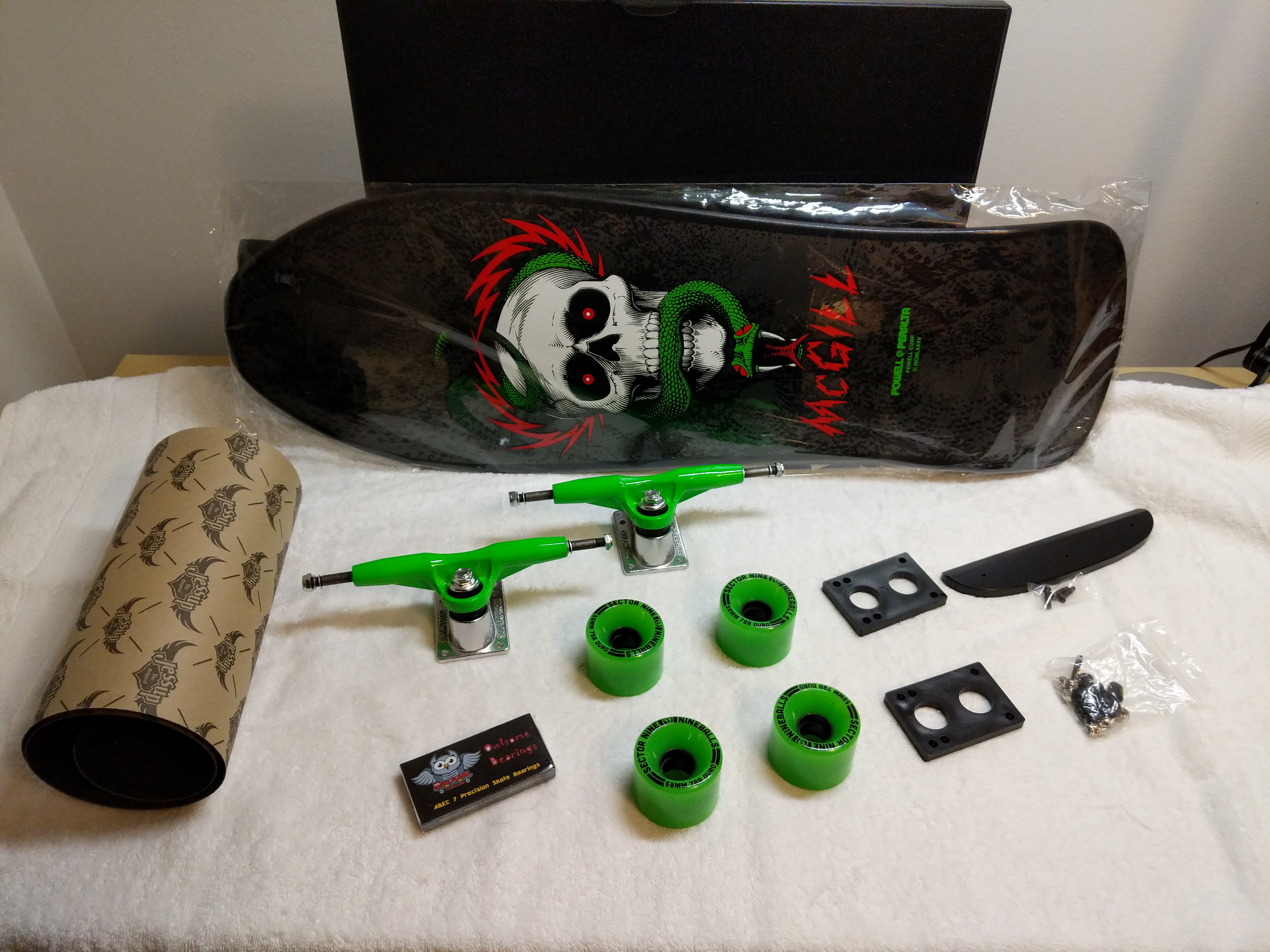
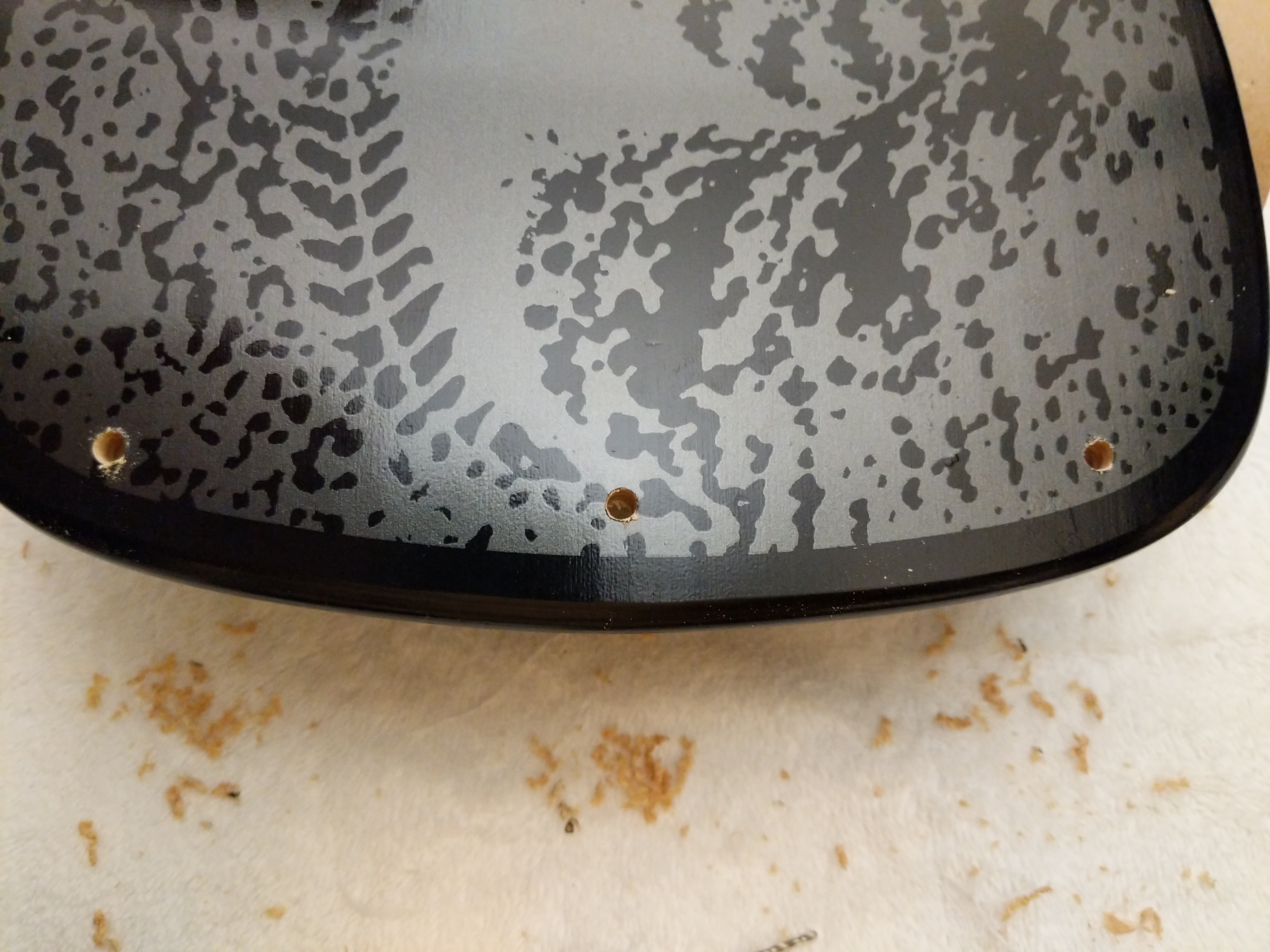
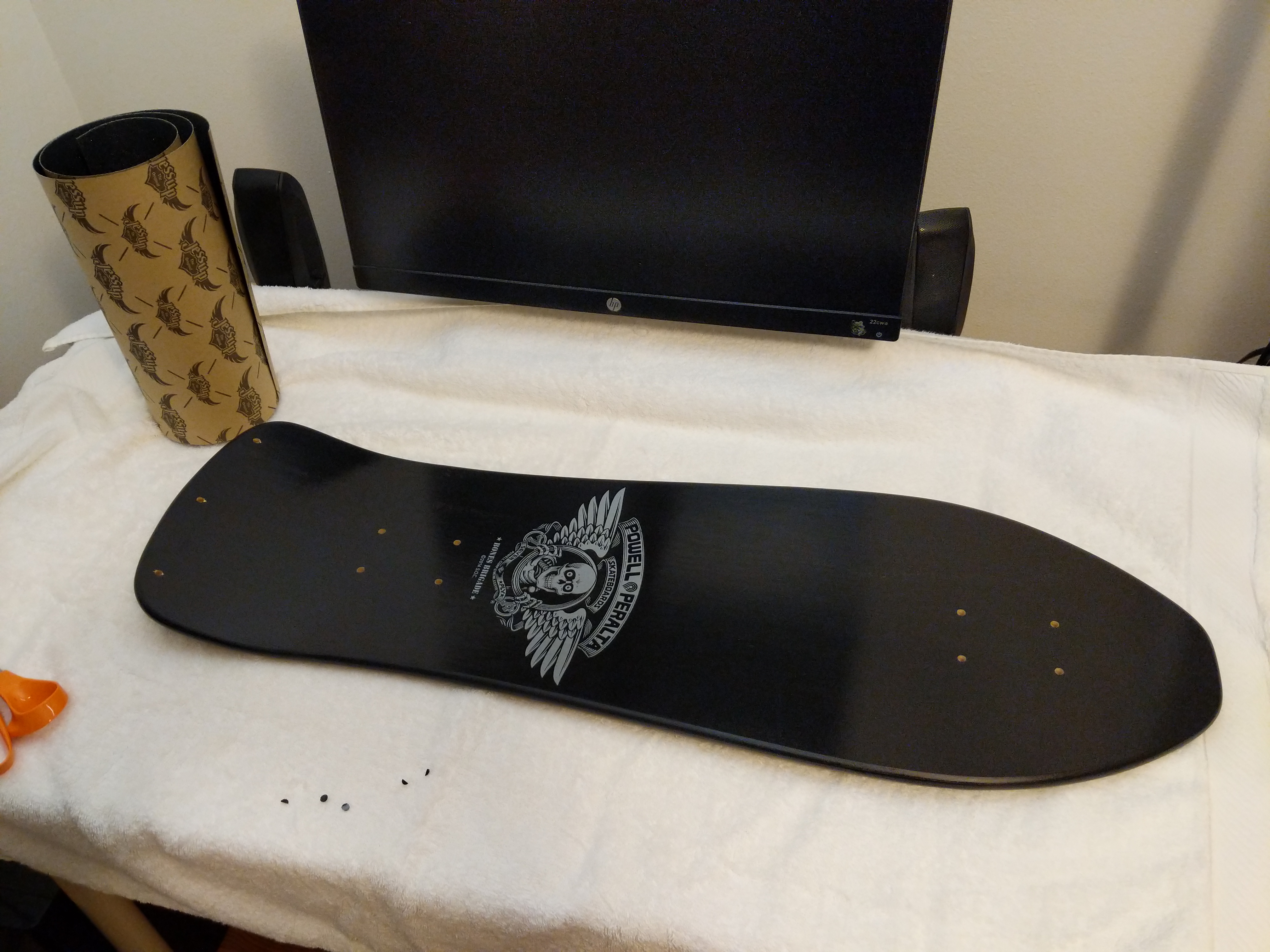
While I couldn’t find my original McGill with a natural finish, I did find this brand new, black dipped, Series #5 re-issue on offer by a seller in Puerto Rico. We negotiated a best offer price, and I received it before anything else.
I picked up a Gullwing Pro III trucks, wheels, bearings, risers, hardware combo from Raptorunner in Riverside, CA, and I ordered a Powell Peralta Tailbone and Jessup grip tape (and a helmet and pads) from TGM Skateboards in Mount Clemens, MI.
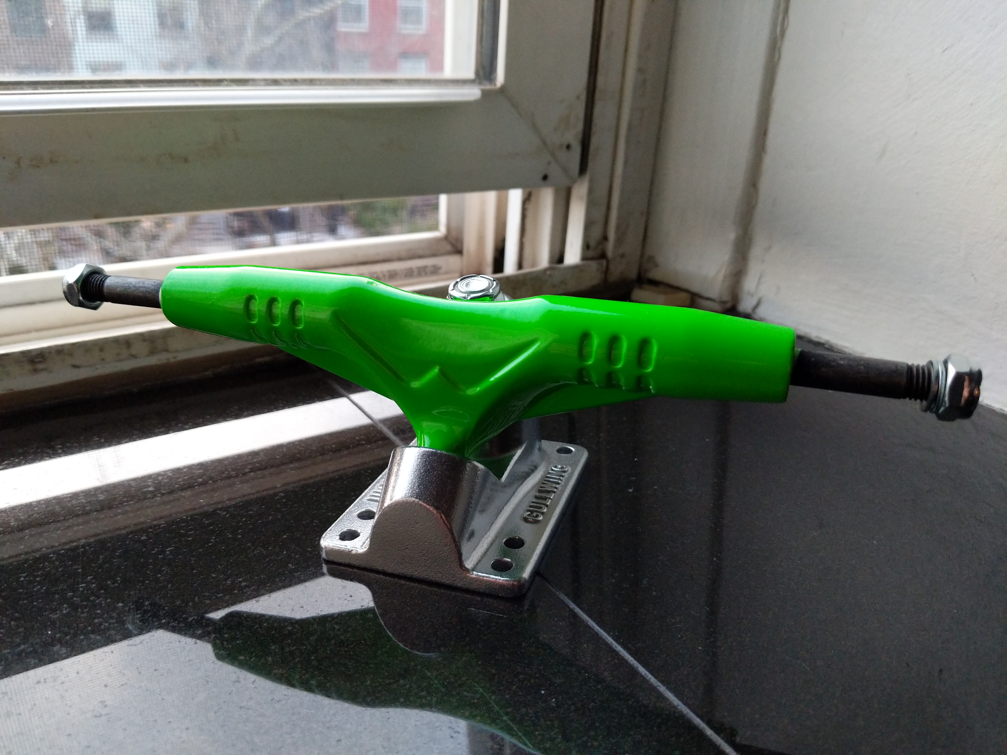
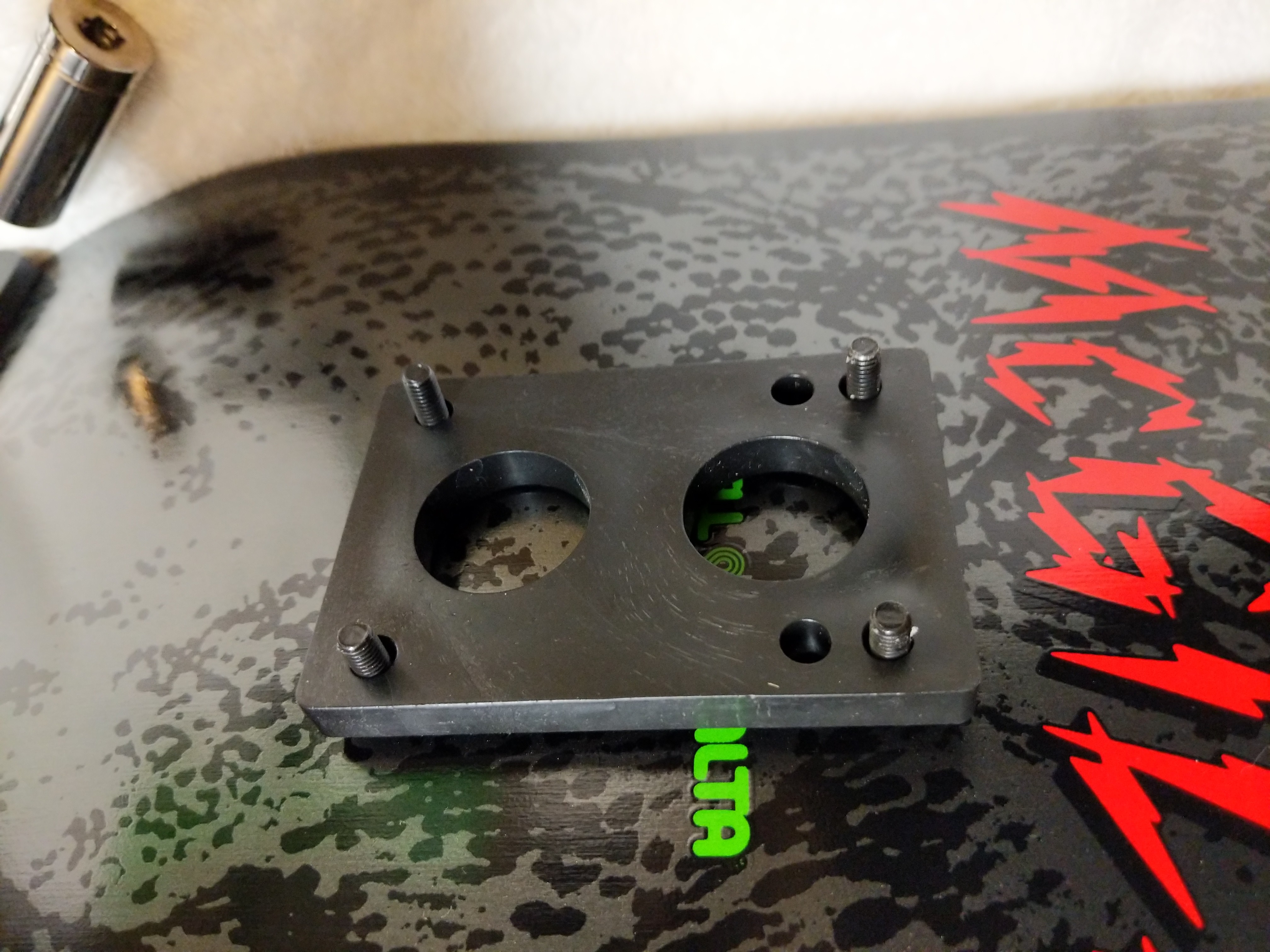
My original Gullwing Pro III trucks were cherry red and stood out well against the natural grain of the board. I liked these new 9″, 155mm neon green ones, because they stand out against the black background on the new, black McGill deck. Also, my re-issued McGill deck uses the old truck bolt pattern, so I chose between these (note that the base plate has six bolt holes instead of four–to accommodate both old and new bolt patterns) and Independent Stage 11 169mm trucks. Ultimately, I opted for the Gullwings since I skated with them before.
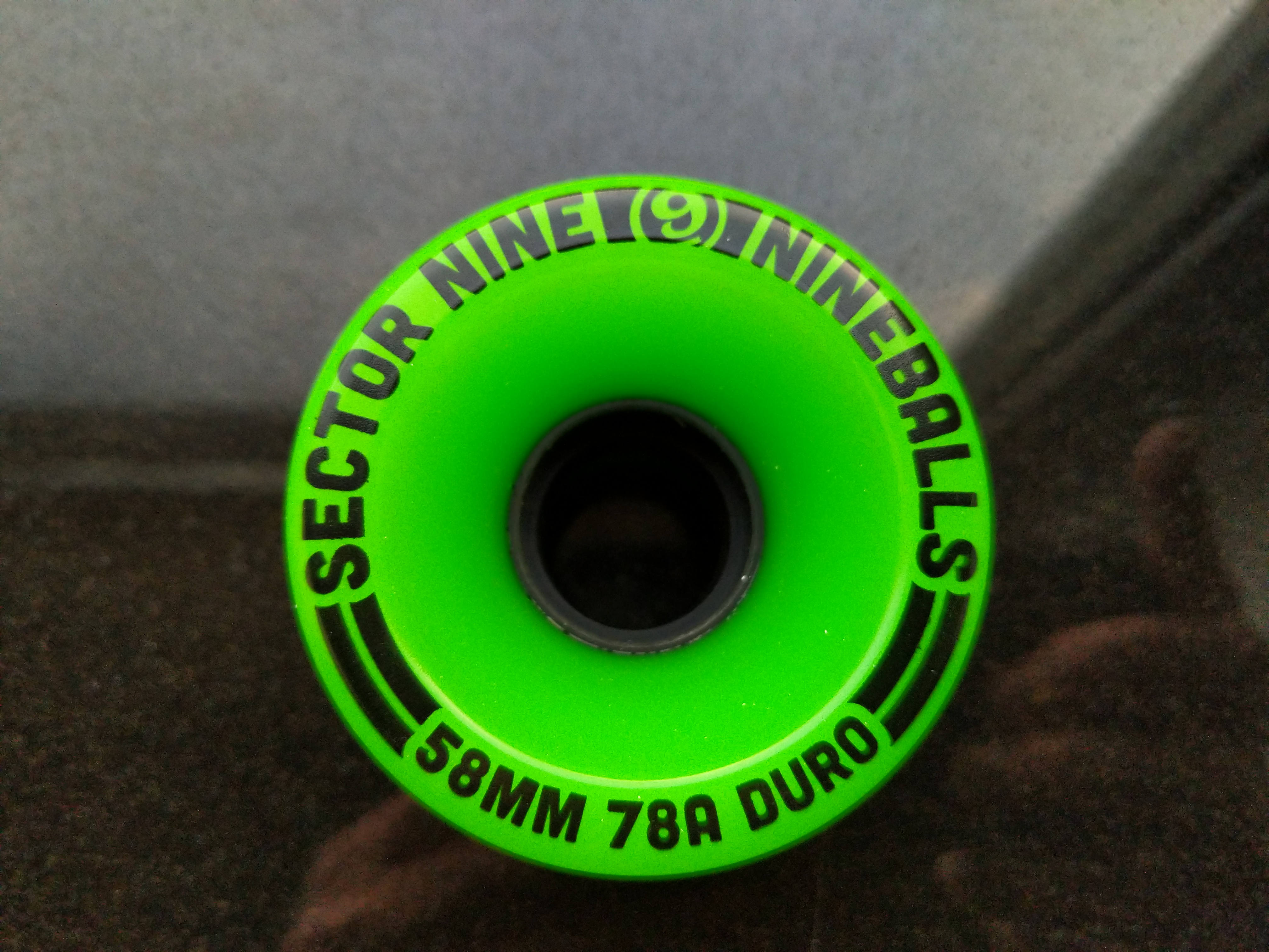
Raptorunner had several different truck, wheel, and hardware bundles. I chose this one, because it had these Sector Nine Nineballs wheels. They aren’t too big (I would have preferred 56mm) and they are real soft (78a), which will be good for the street crusing that I intend to use the skateboard for.
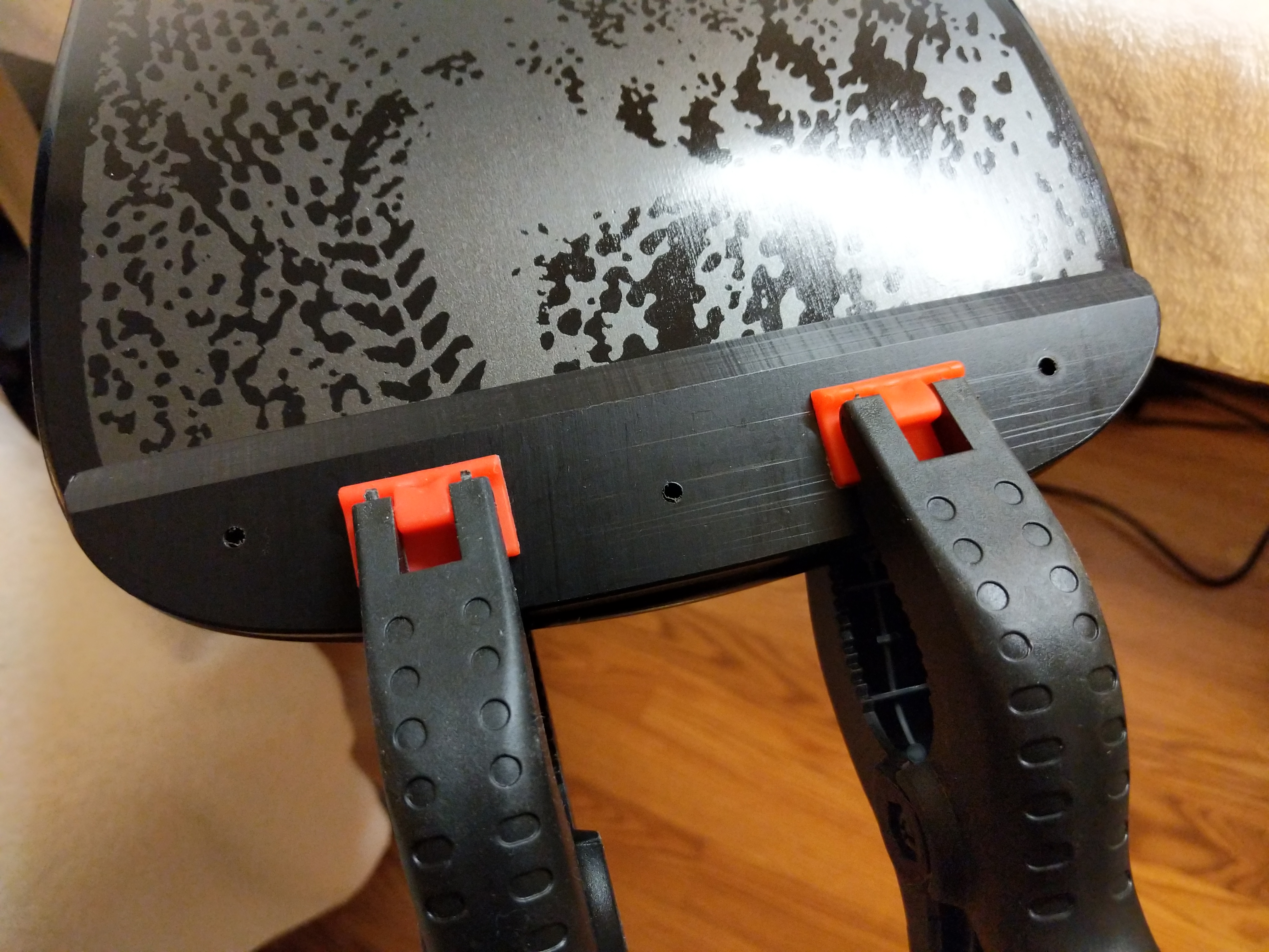
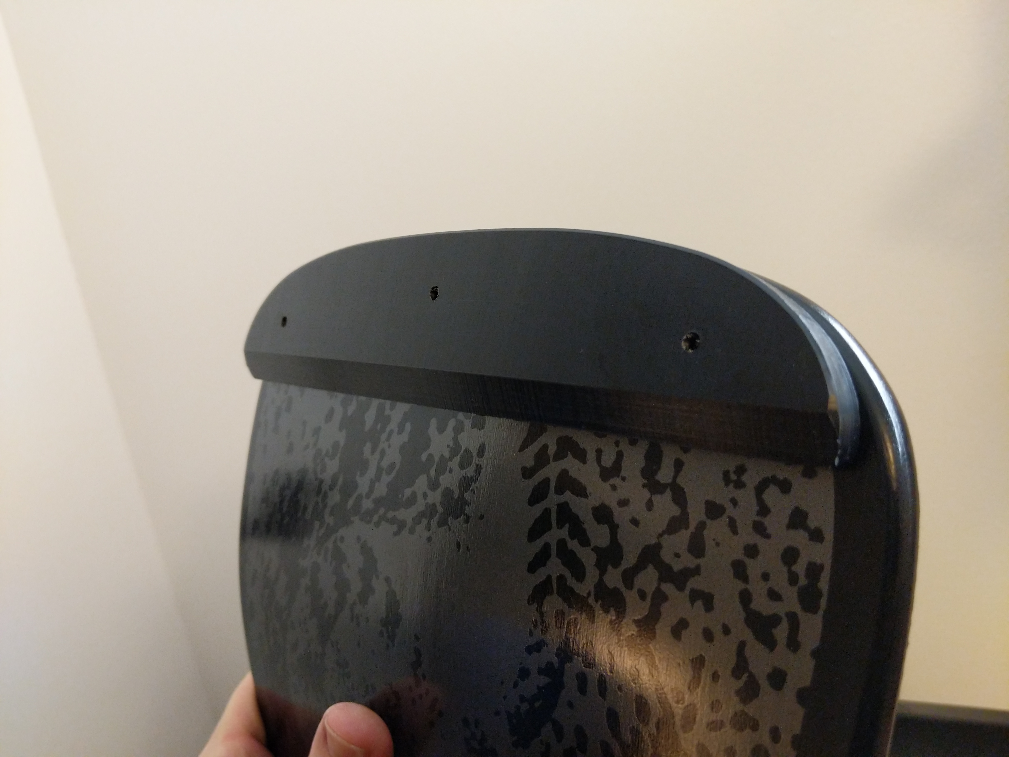
To begin my skateboard’s assembly, I began with the Tailbone before applying the grip tape. I clamped the tail guard to the bottom of the deck’s tail and measured to ensure it was centered.
Then, I used a small drill bit to lightly mark where I should drill the larger holes for the wood screws that will go through the top of the board into the Tailbone.
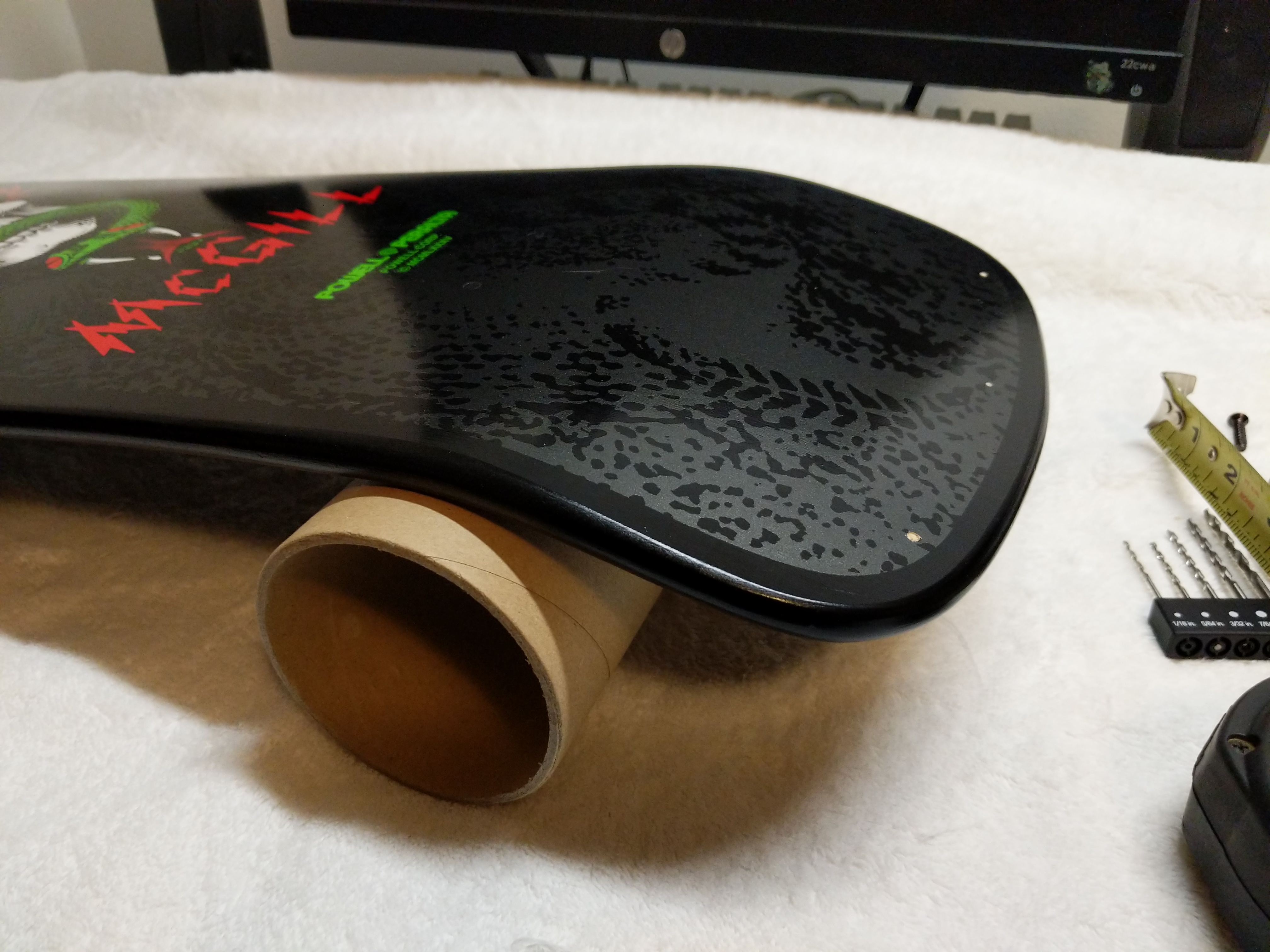
I used the grip tape shipping tube to support the deck while I was drilling.
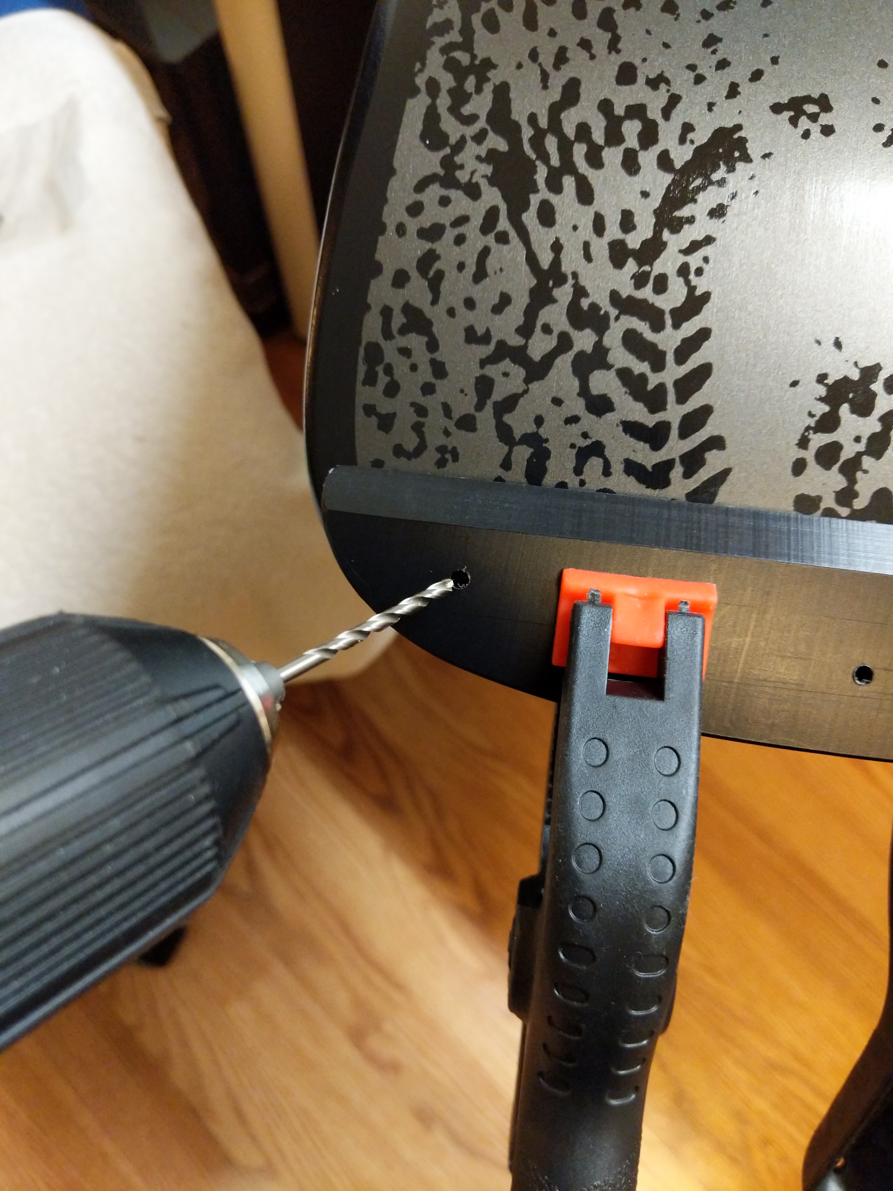
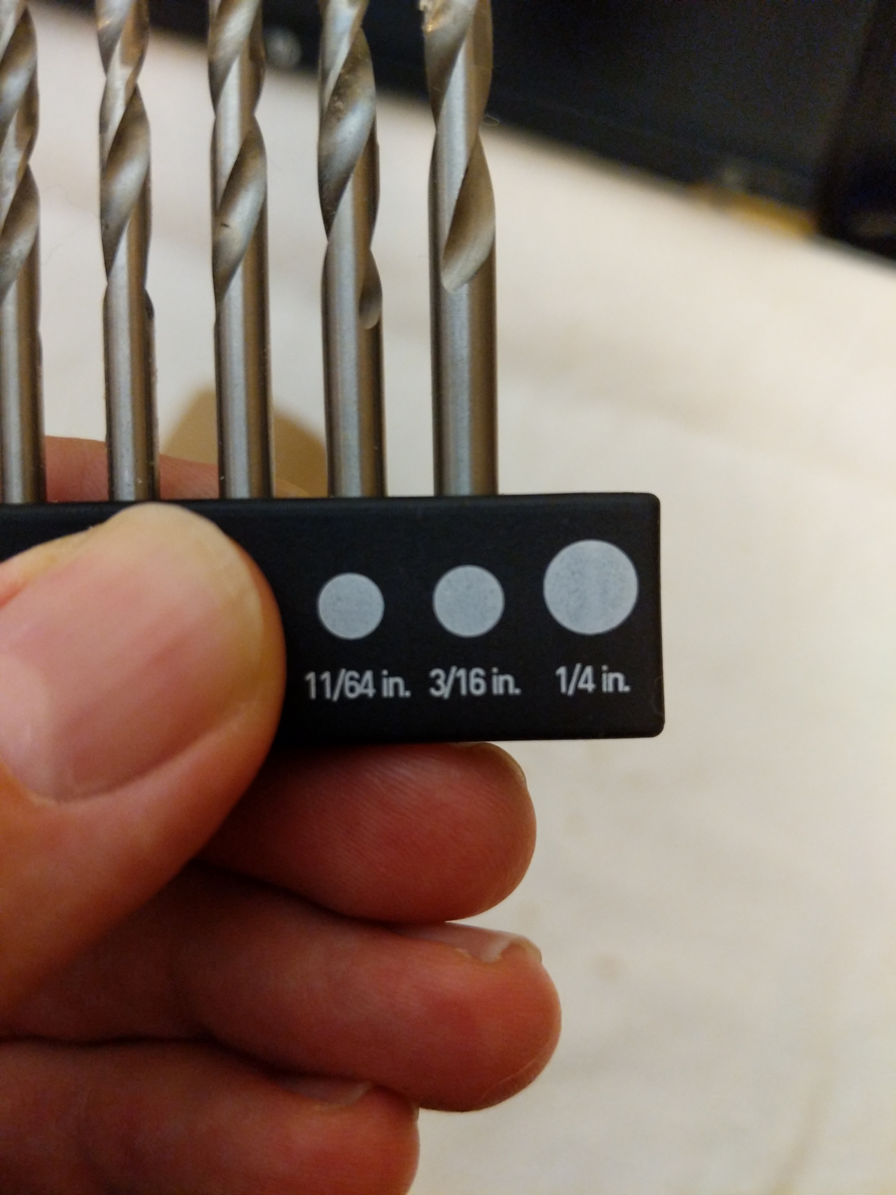
Powell-Peralta’s instructions for the Tailbone call for a 7/32″ drill bit. Unfortunately, I didn’t have one in this size. I didn’t want to go with a larger hole (1/4″), so I tried the 3/16″ bit. Luckily, this was more than enough room for the wood screws to pass through the board without biting and then go into the Tailbone.
Using my earlier marks, I drilled three holes through the deck’s tail. These will be used later for mounting the Tailbone.
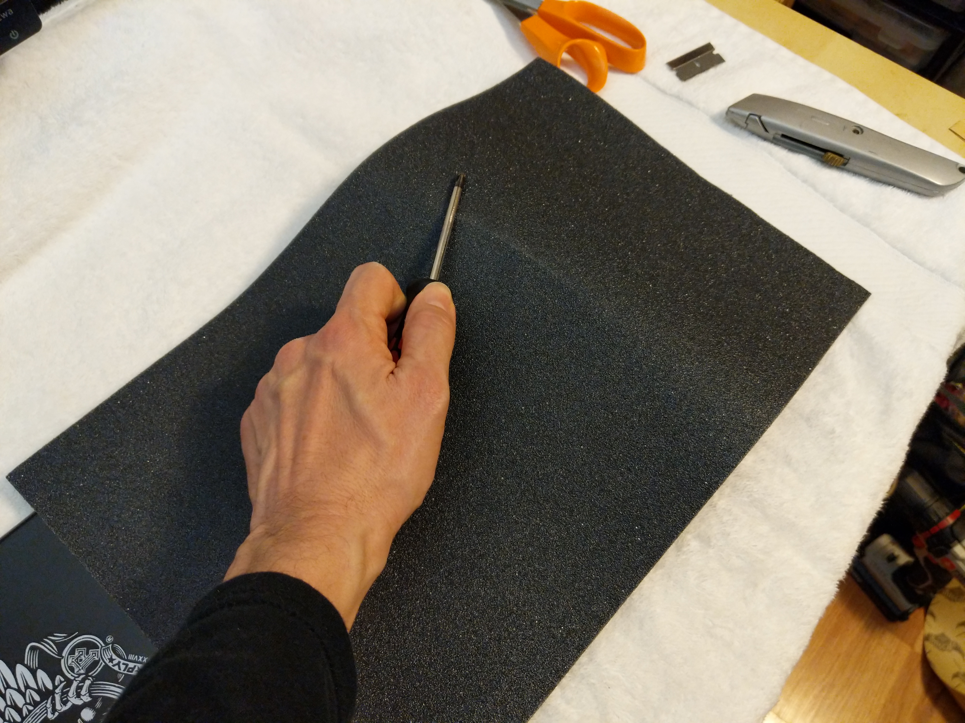
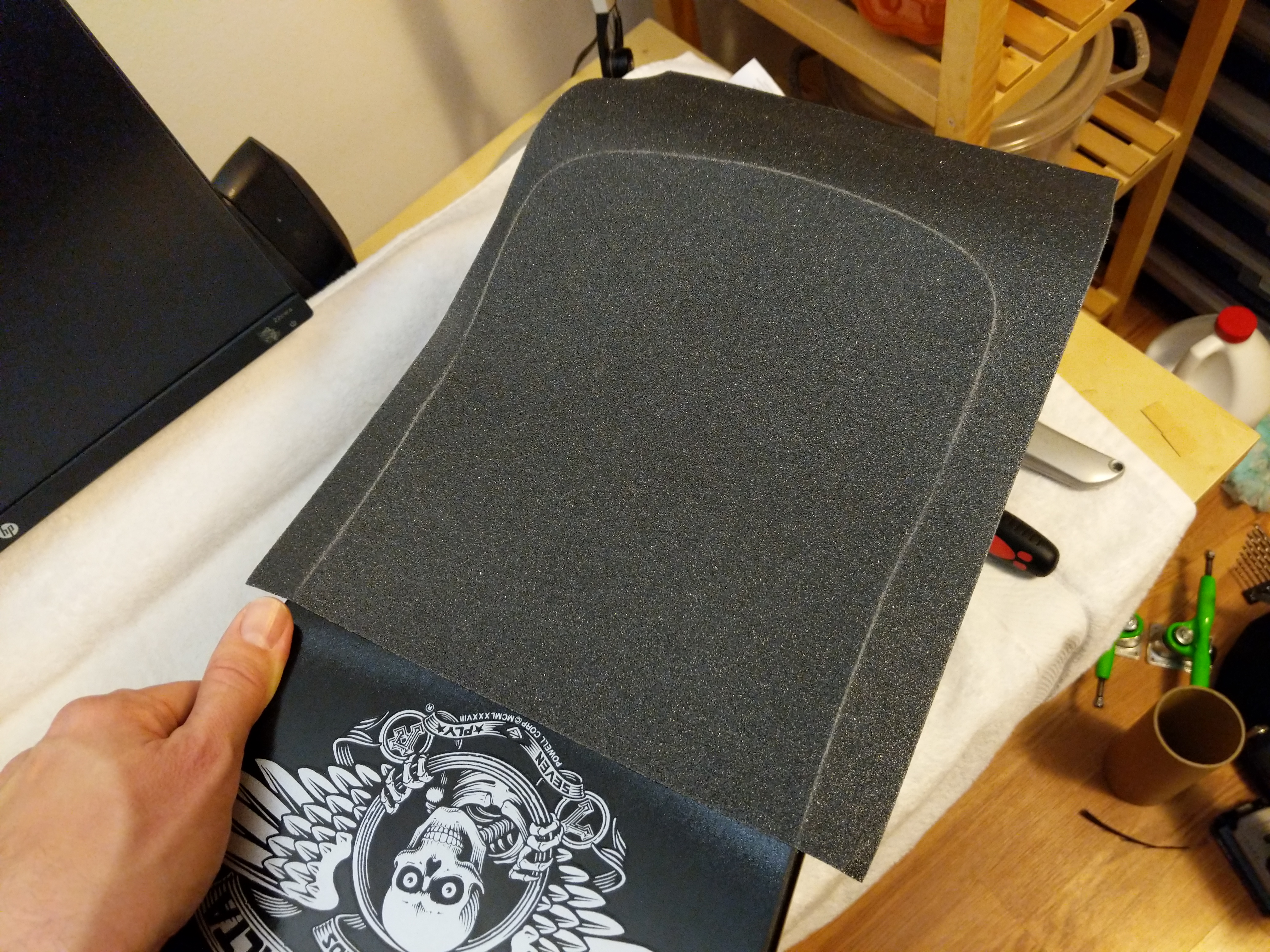
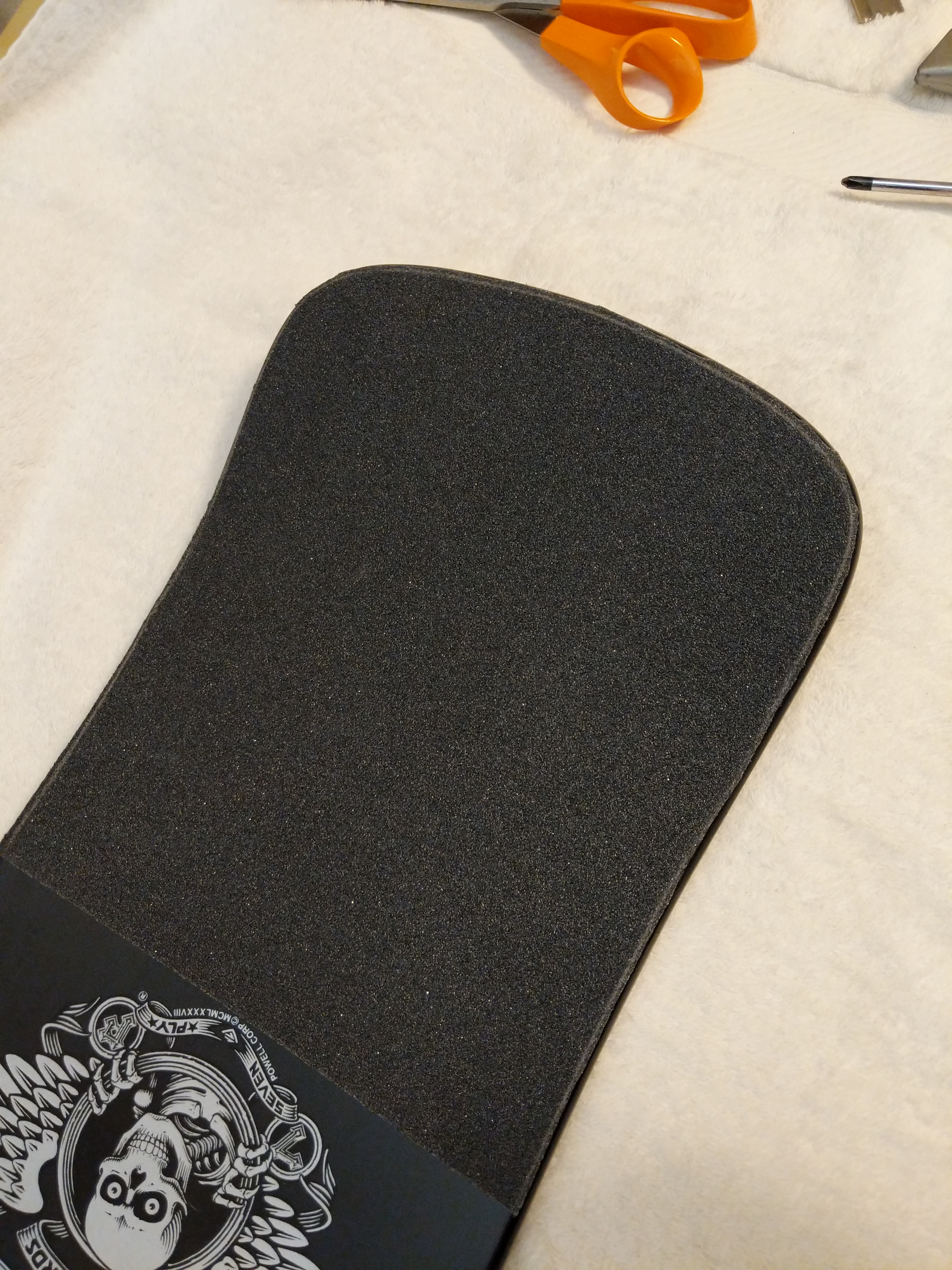
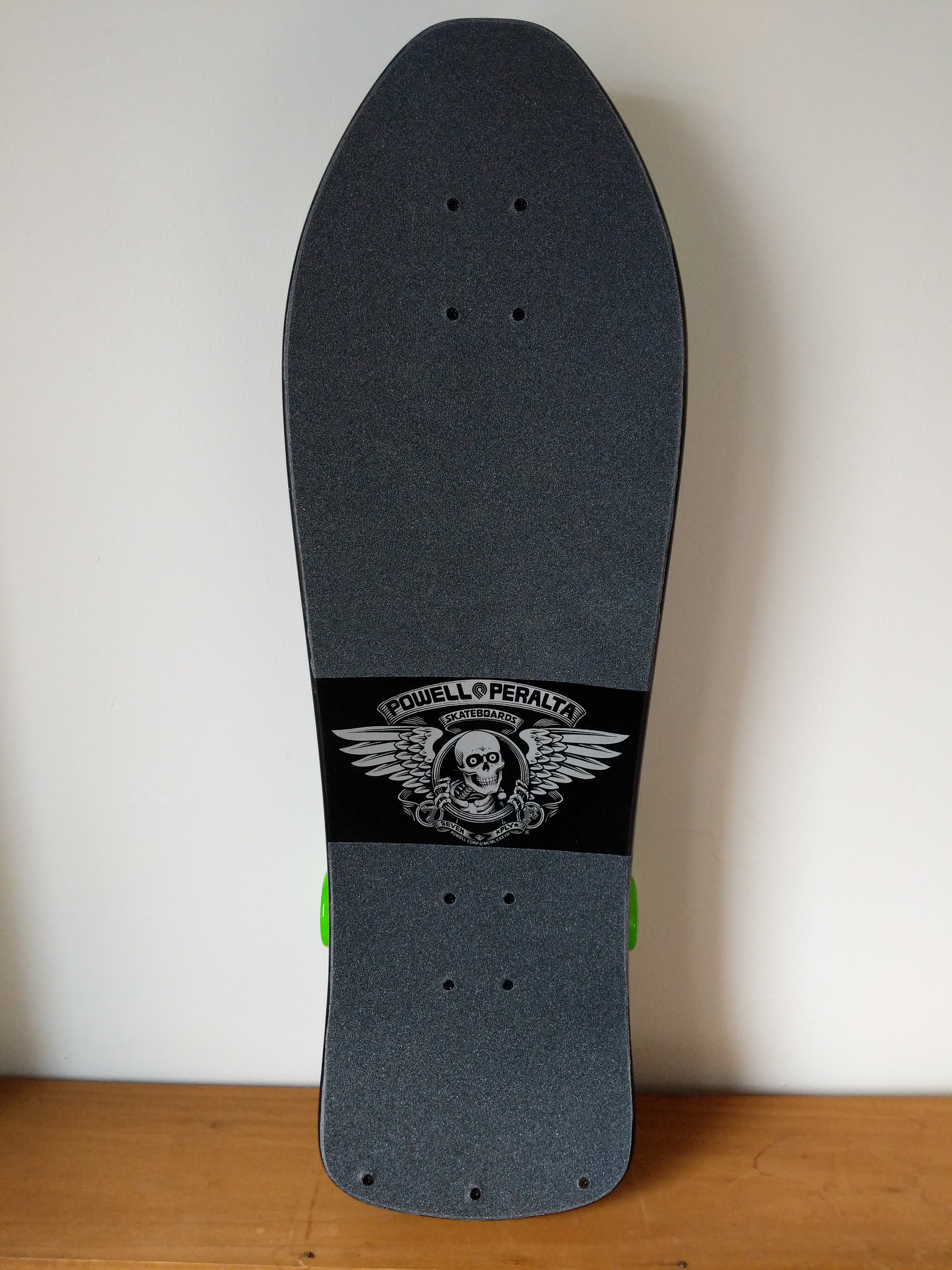
Before mounting the Tailbone, I applied the Jessup grip tape. I bought 10″ wide grip tape, which is just barely wide enough to give some room for error with the front of the deck. If I had to do over again, I would have opted for the 11″ wide grip tape.
I wanted the Bones Brigade logo to appear on the top of the deck, so I needed to apply two sections of grip tape–one above it towards the nose and one below it towards the tail. I measured these lengths twice and cut the length of grip tape into two sections allowing some room for error in terms of length. I used the pre-cut edges as the beginning of application above or below the Bones Brigade logo. I slowly lowered and pressed the grip tape to the deck so as to avoid any air bubbles under the tape.
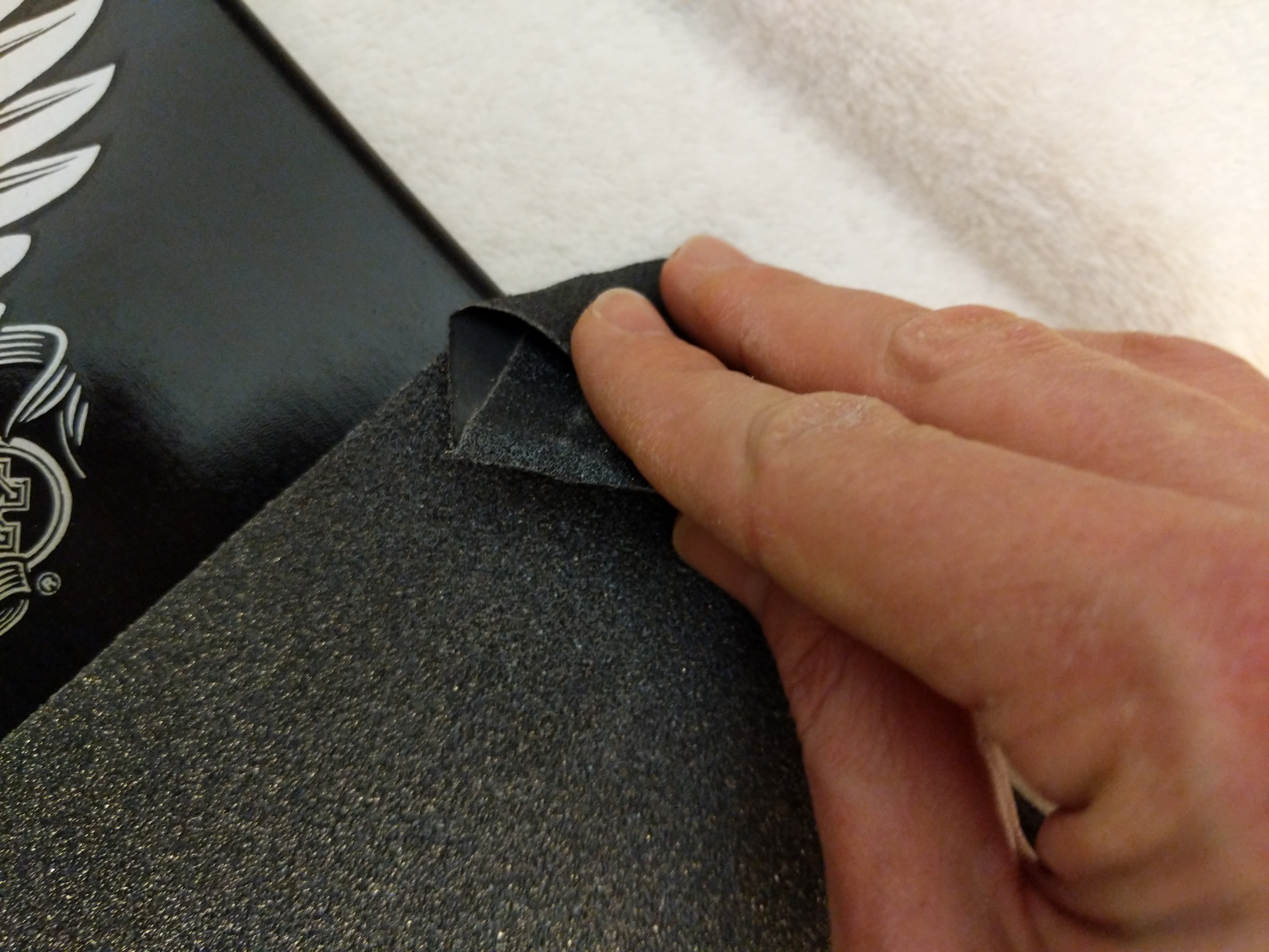
With the tape applied, I used the barrel’s edge of a screw driver to draw a scoring line around the edge of the skateboard deck.
Then, I used a razor blade held from underneath the board to follow the edge of the board and cut the excess grip tape off along the scoring line.
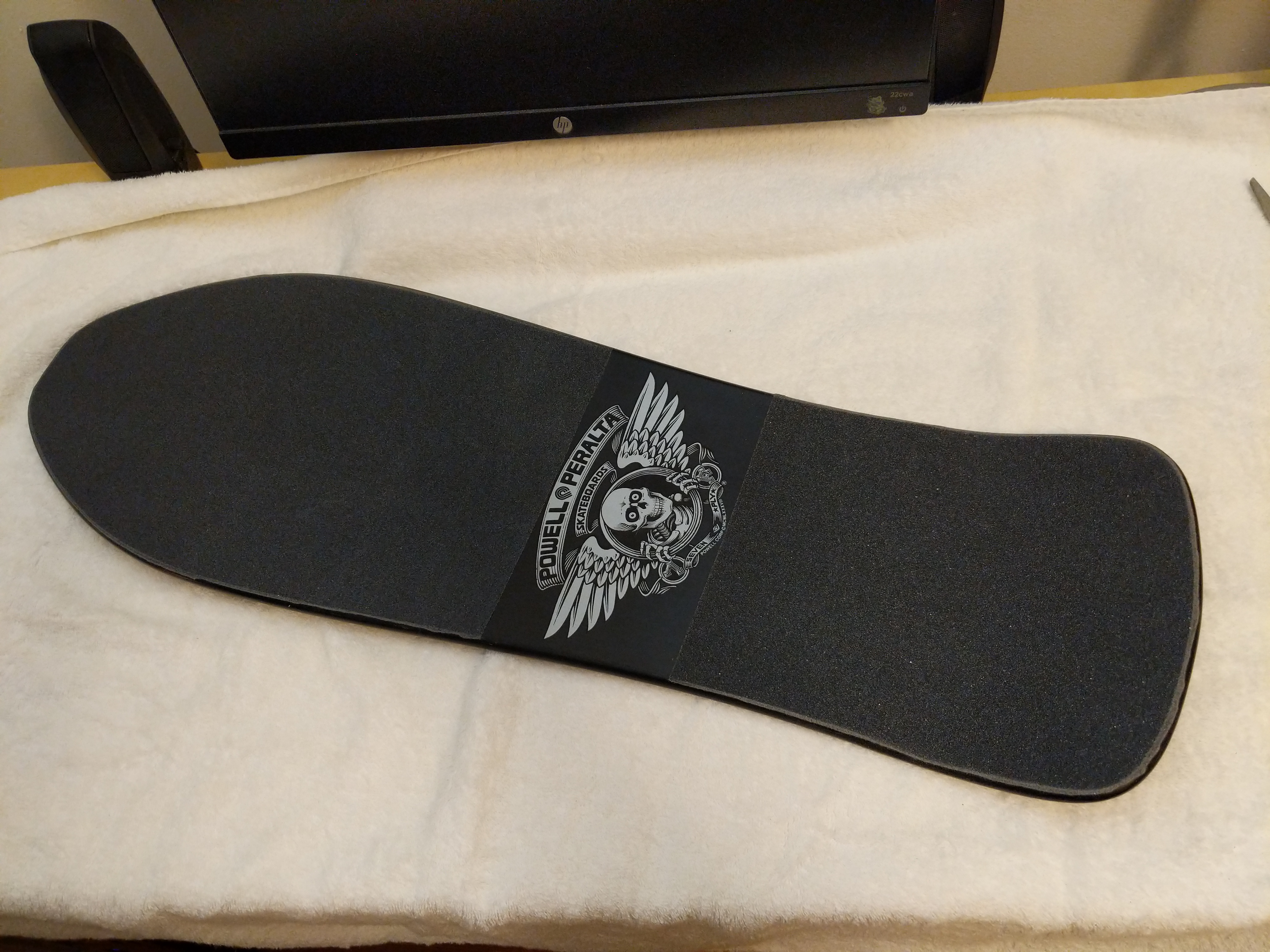
Next, I pressed the grip tape down around the edges of the deck.
I ran a rolled up piece of excess grip tape around the edge of the deck to give the grip tape a clean edge all away around.
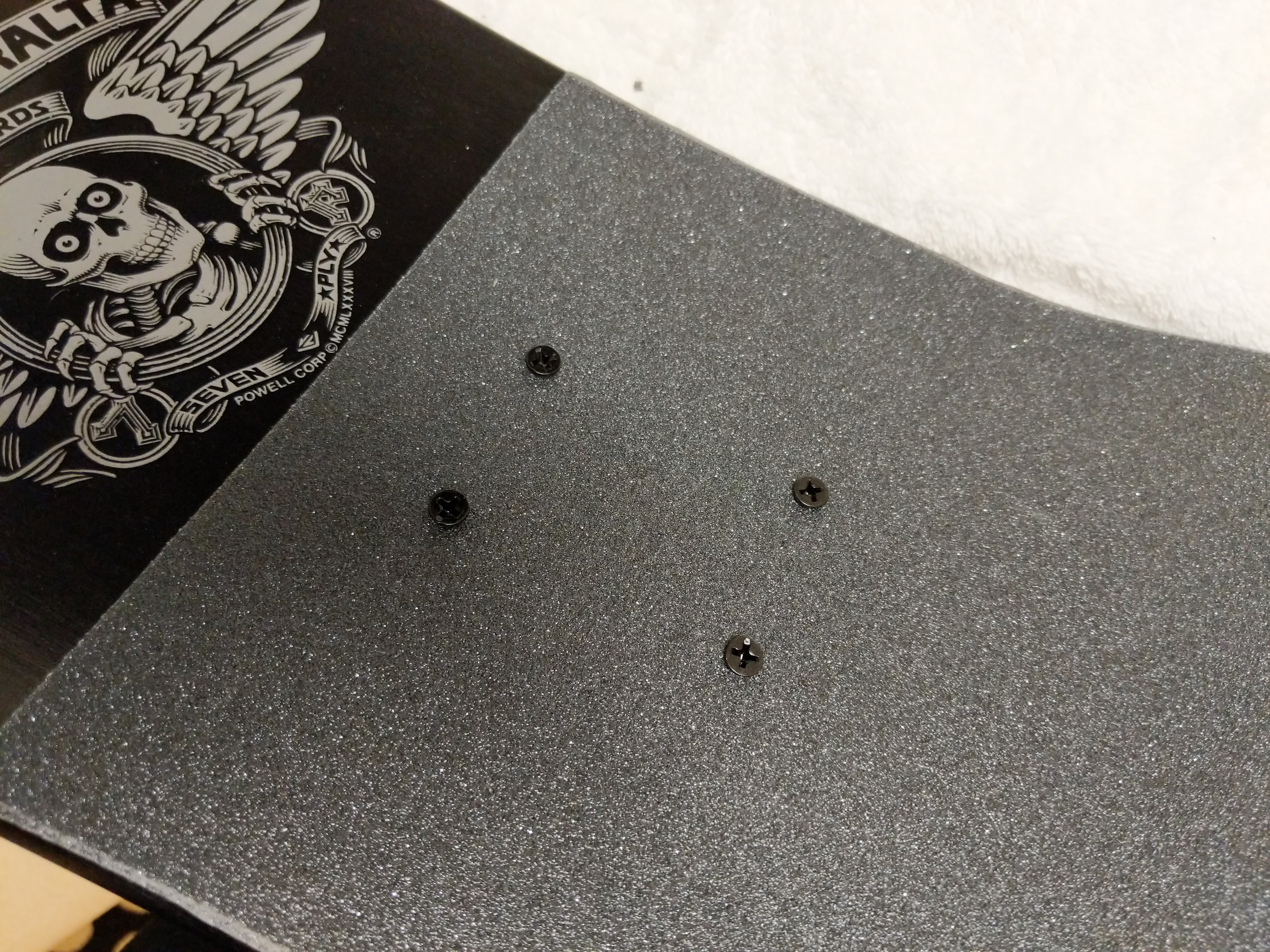
With the grip tape applied, I used a screw driver to punch through all of the holes in the deck for the trucks and Tailbone.
Next, I installed the tailbone by pushing through wood screws and matching them to the holes in the Tailbone.
While I had a cordless drill on-hand, I preferred to install these screws by hand. I was afraid of over torquing the screws and losing grip in the Tailbone’s plastic. Installing the screws by hand allows me to feel them dig into the plastic and maintain a secure hold on the Tailbone through the deck without stripping out plastic.
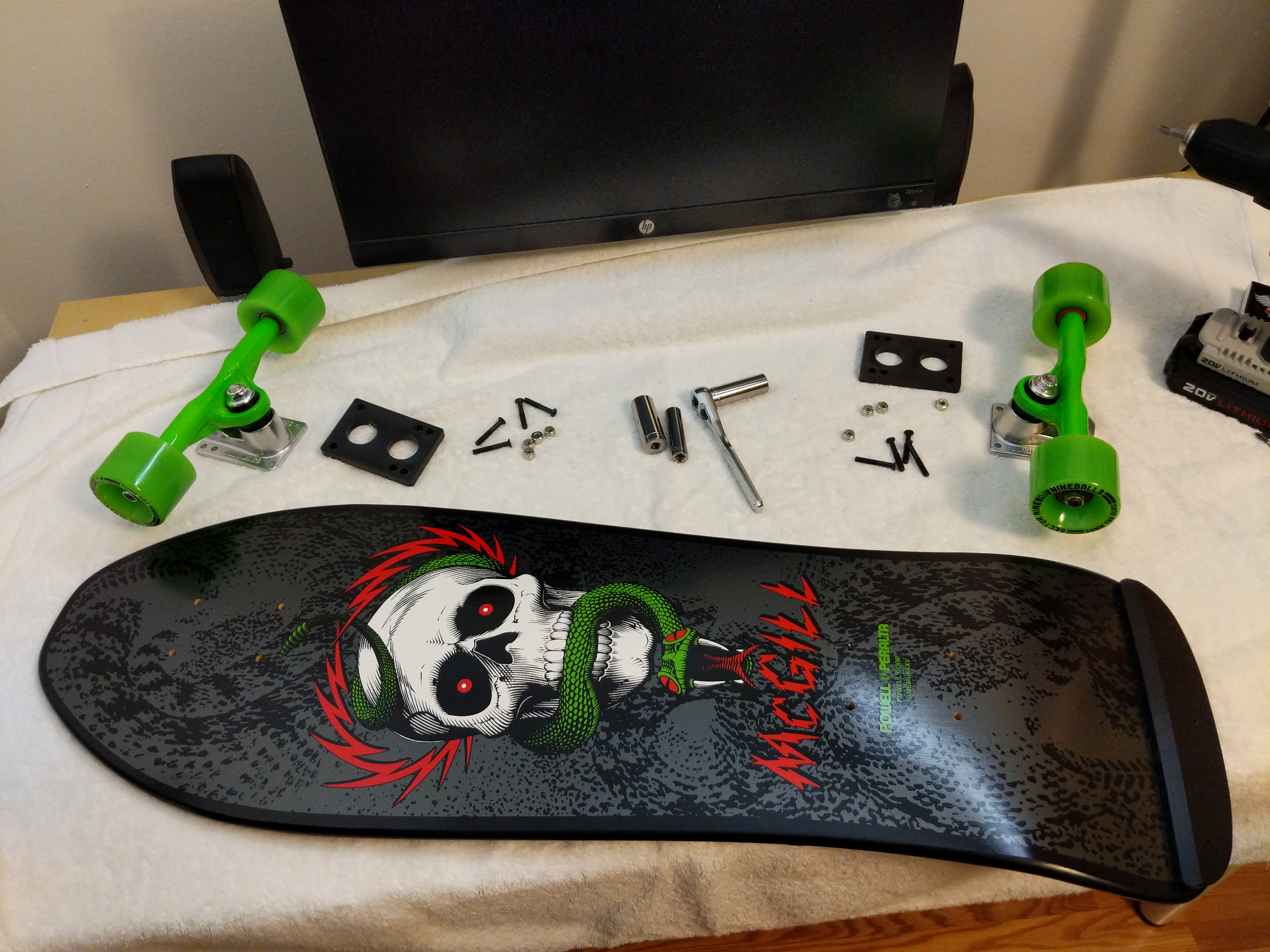
The final stage of the assembly involves the trucks, wheels, bearings, and 1/4″ risers. I laid all of these parts out to make the assembly quicker. For some of the assembly, I used the cordless drill with a Philips head driver, and I had my 1/4″ drive tall sockets in 3/8″ (for the truck mounting bolts) and 1/2″ (for the truck’s axle bolts).
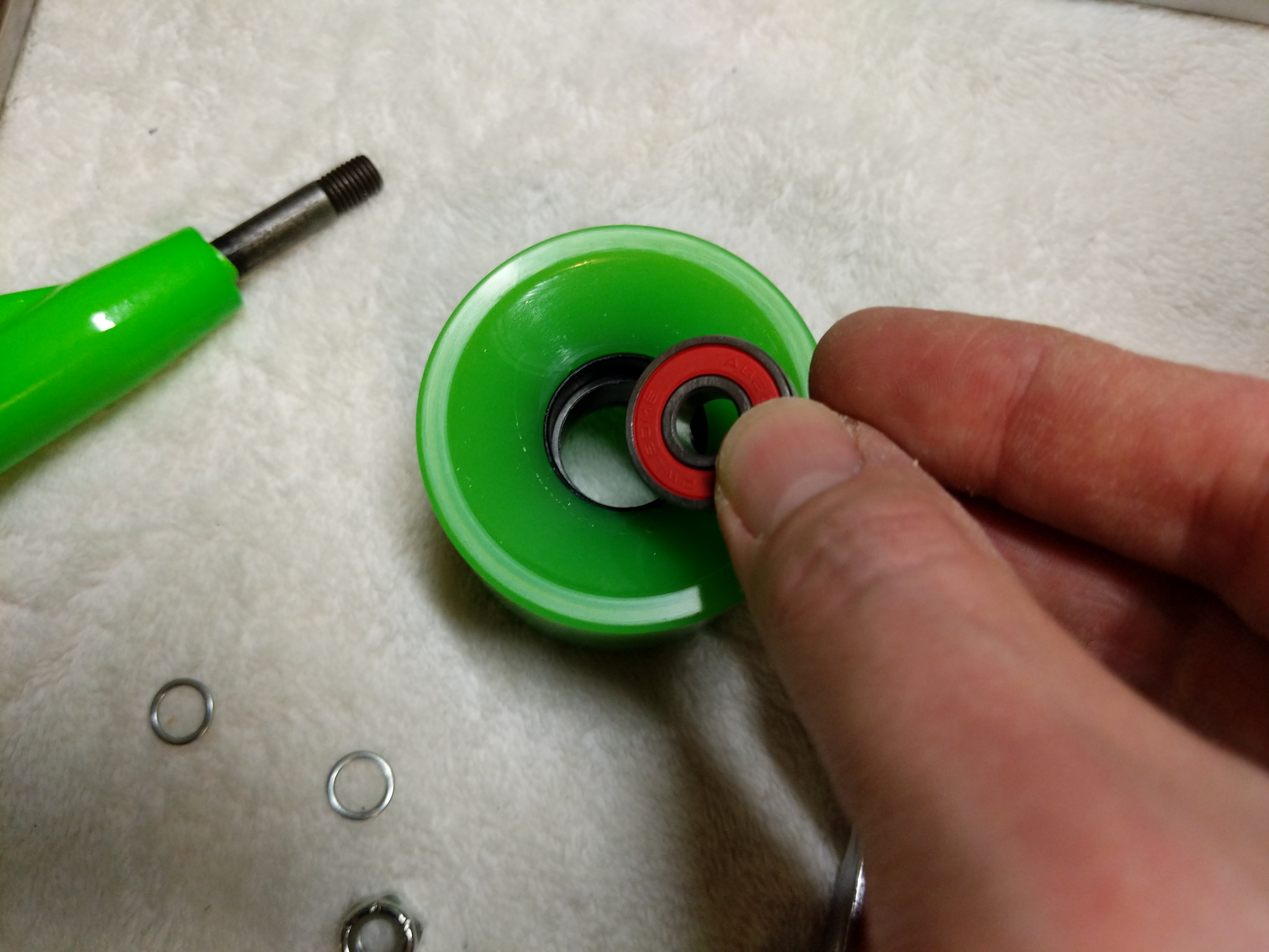
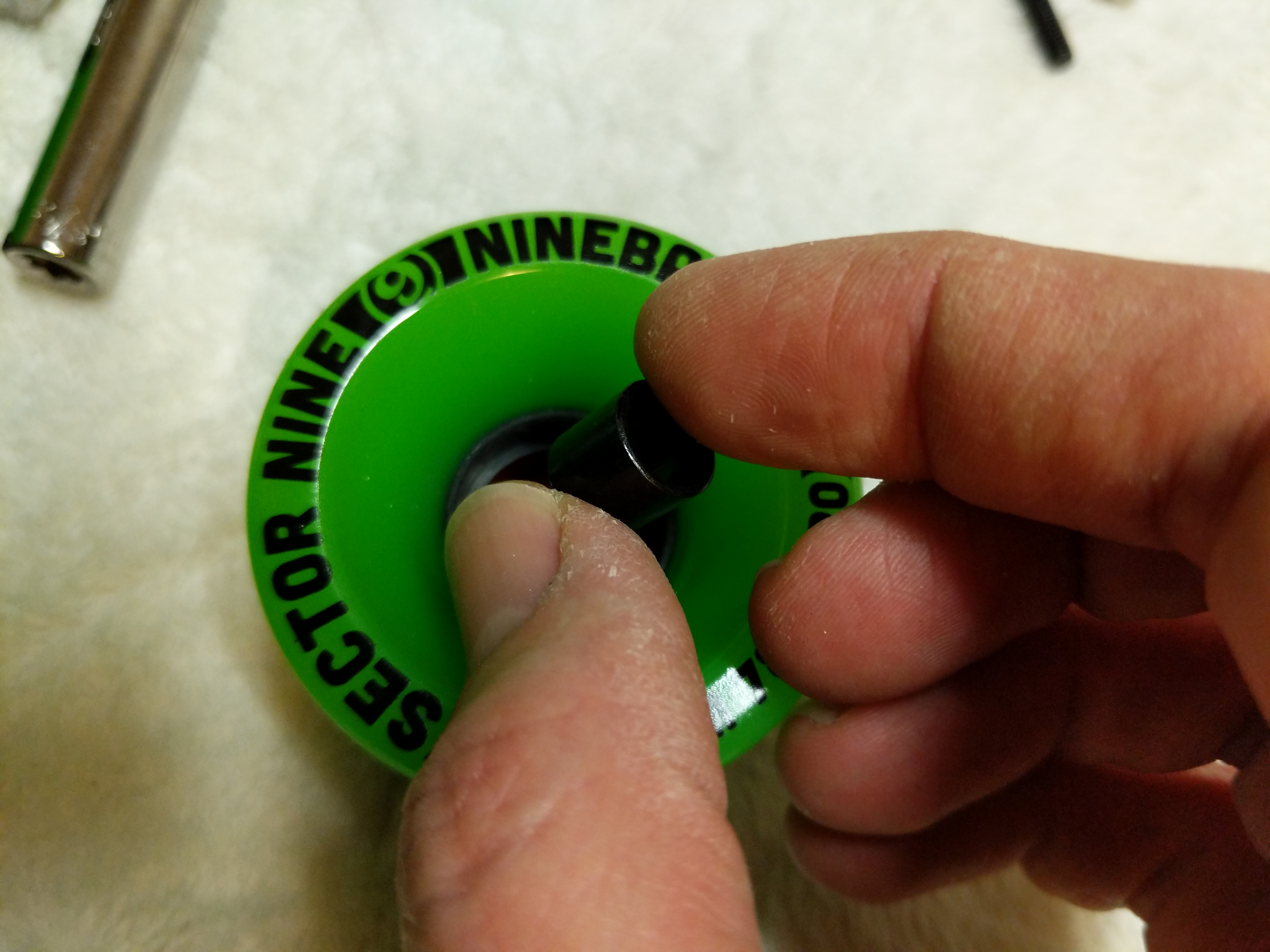
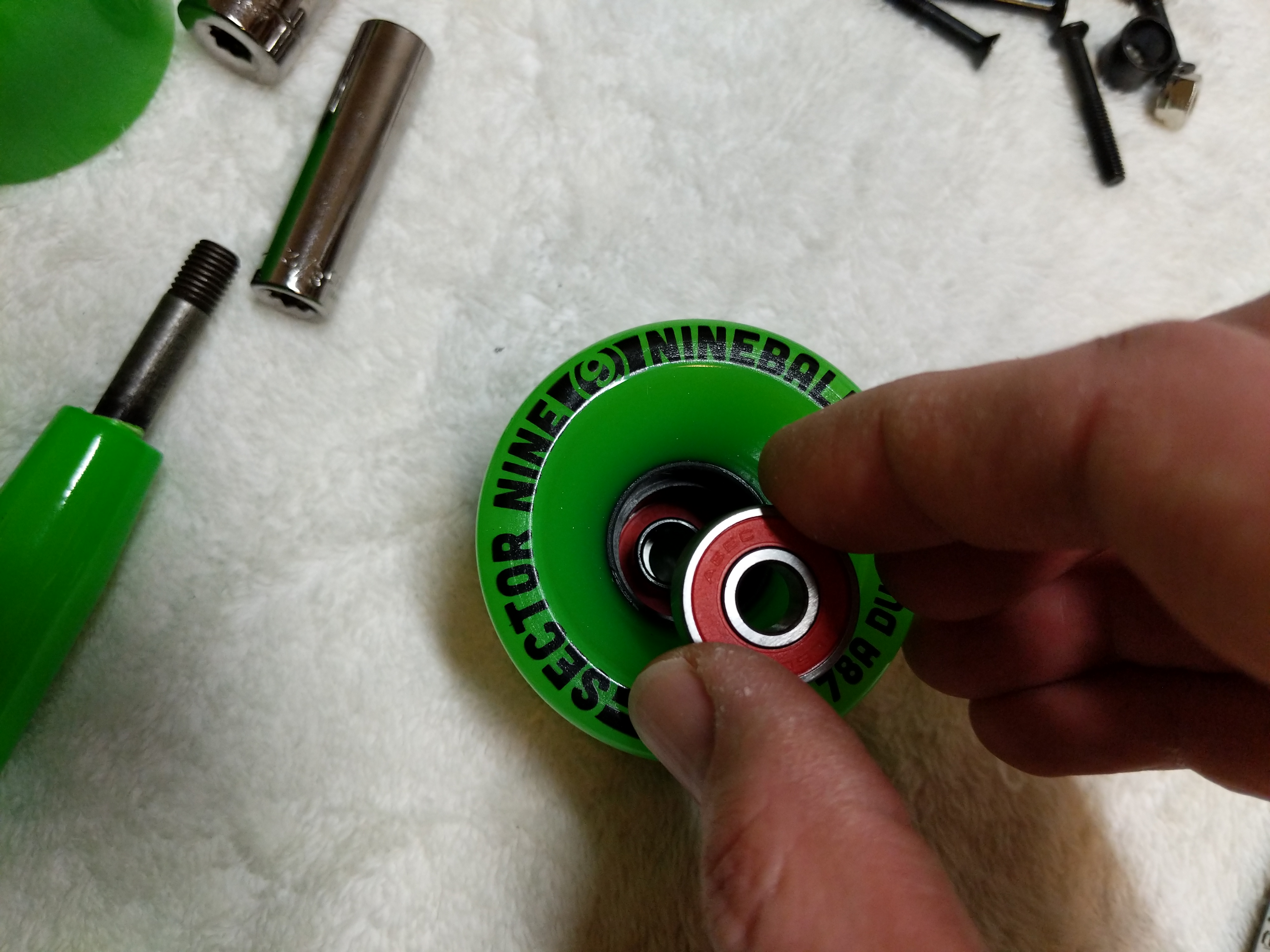
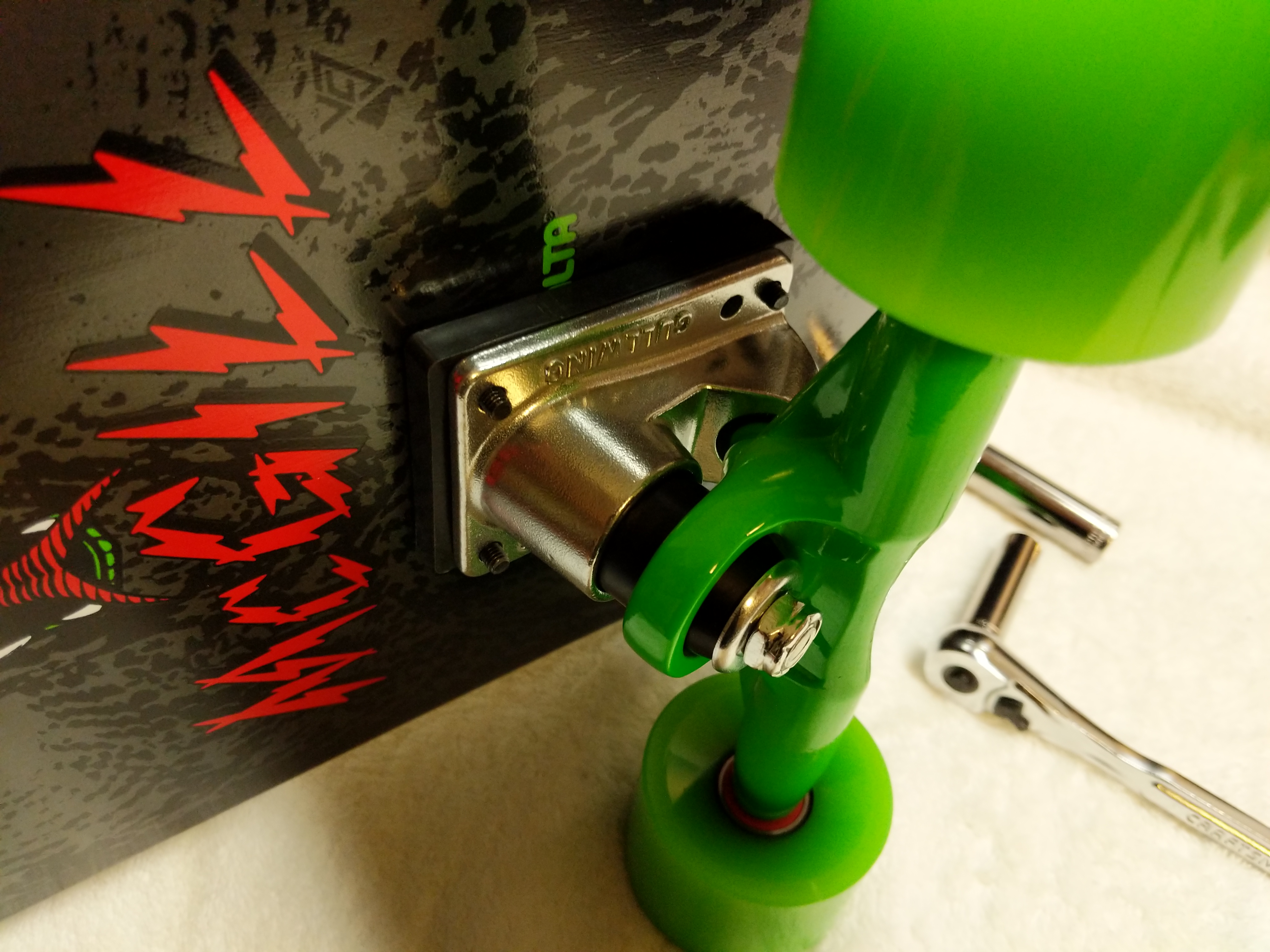
The first task was to install bearings and spacers in each wheel. I placed an Owlsome Precision ABEC 7 bearing assembly into the back of a wheel.
Then, I used one of the trucks to help me press the bearing completely into the wheel so that it is flush with the wheel.
Turning the wheel over, I dropped a spacer on top of the inserted bearing.
Then, I placed another bearing into the front of the front of the wheel over the spacer, and again, used the trucks to help me press the bearing assembly completely into the wheel.
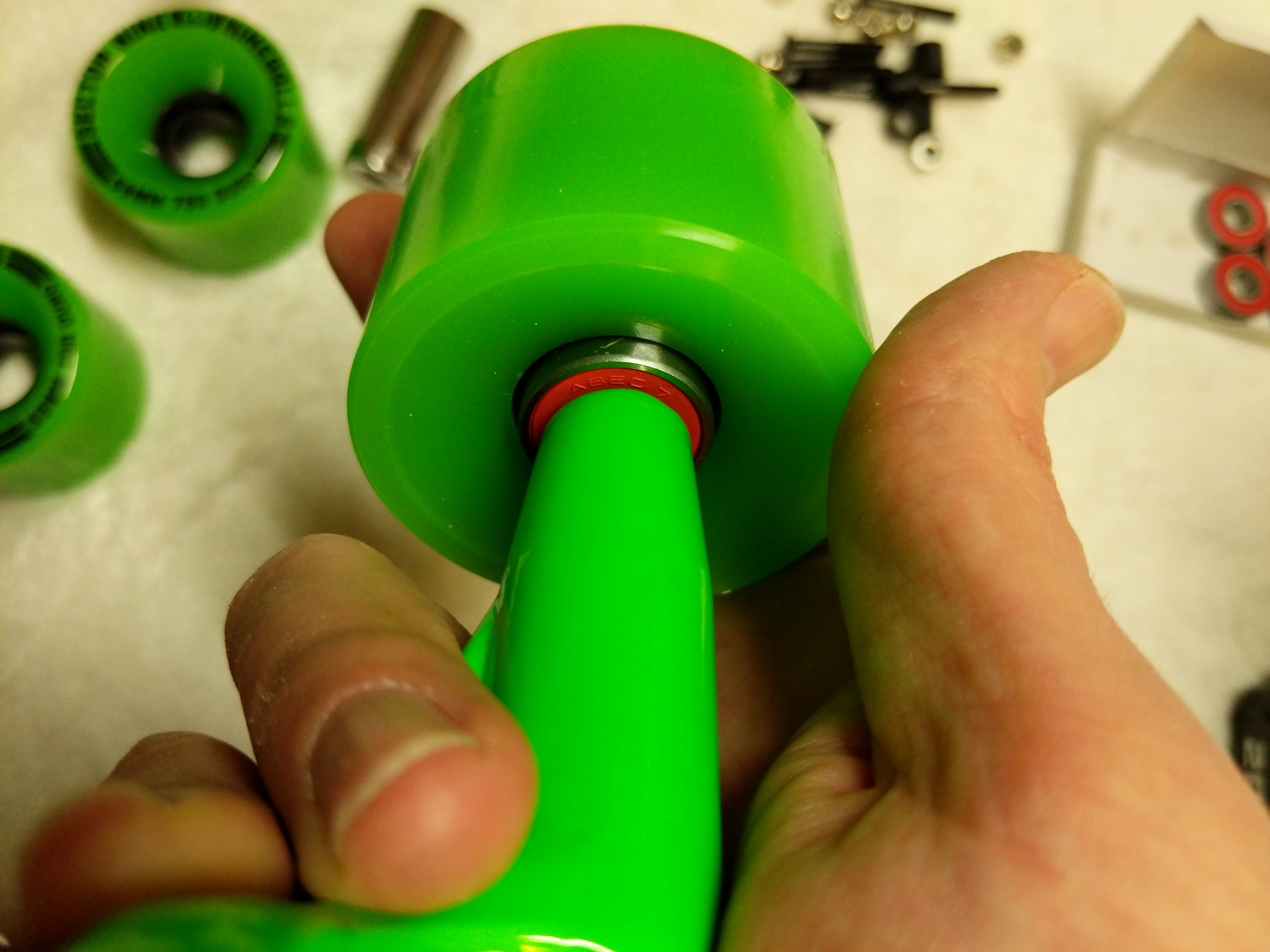
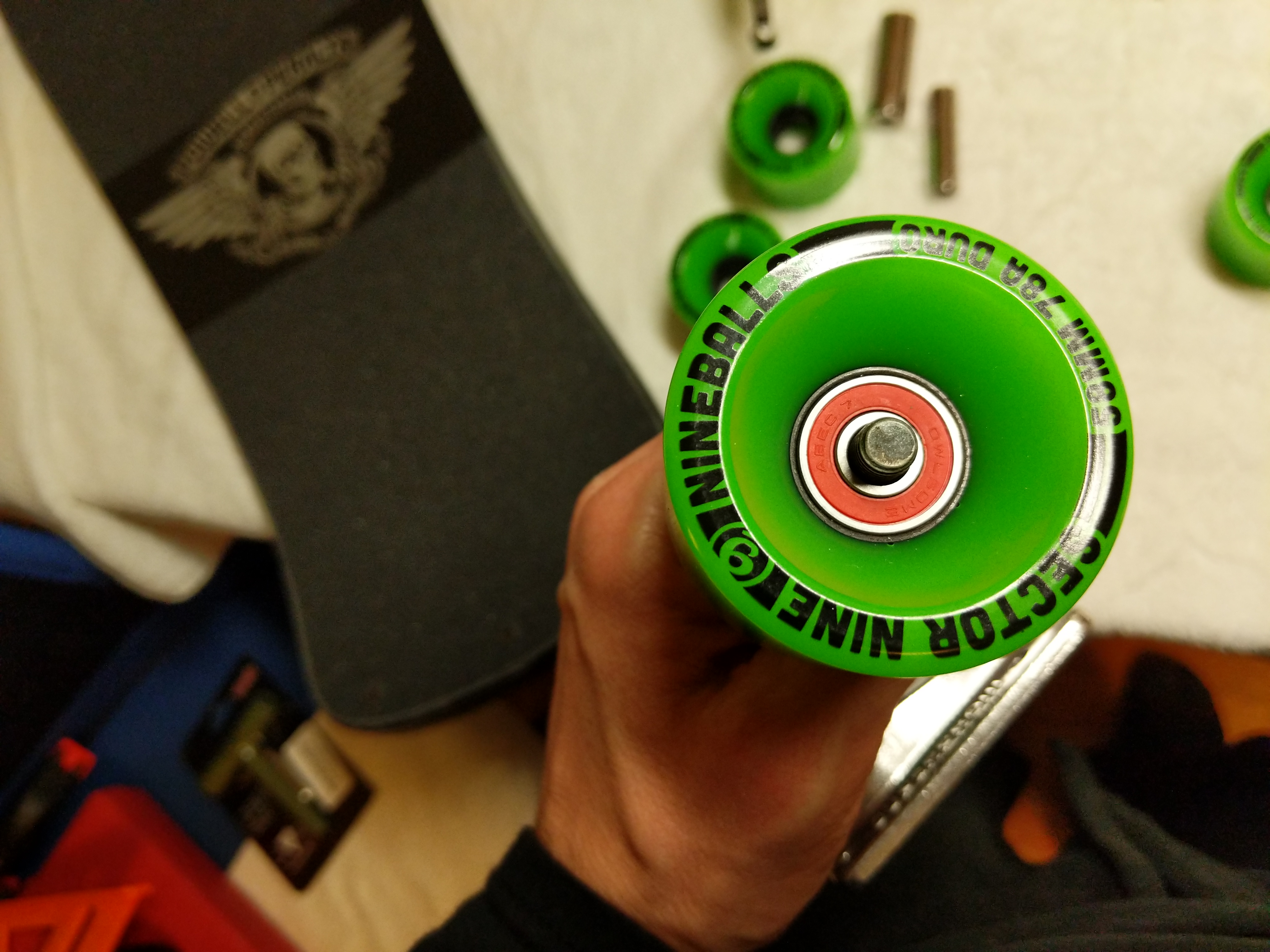
Then, I pulled the wheel off, placed a washer on the axle, followed by the wheel with the front facing outward, another washer, and then the axle nut. I tightened the axle nut by hand with the 1/2″ socket. I left a very slight bit of play for the wheel on the axle.
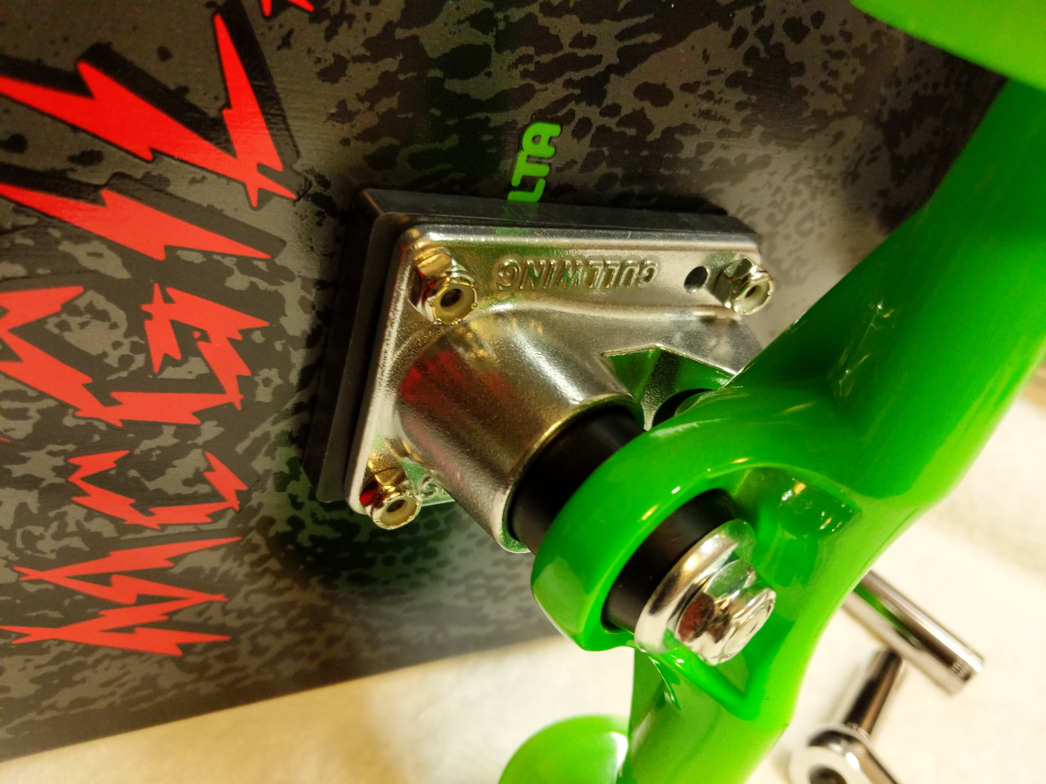
With all of the wheels assembled with bearings and spacers and these installed on the trucks, I was ready to complete assembly of the skateboard by mounting the risers and trucks to the skateboard deck.
First, I pushed the 1 1/4″ truck mounting bolts through the skateboard deck.
Then, I mounted the 1/4″ riser through the bolts on the underside of the skateboard deck.
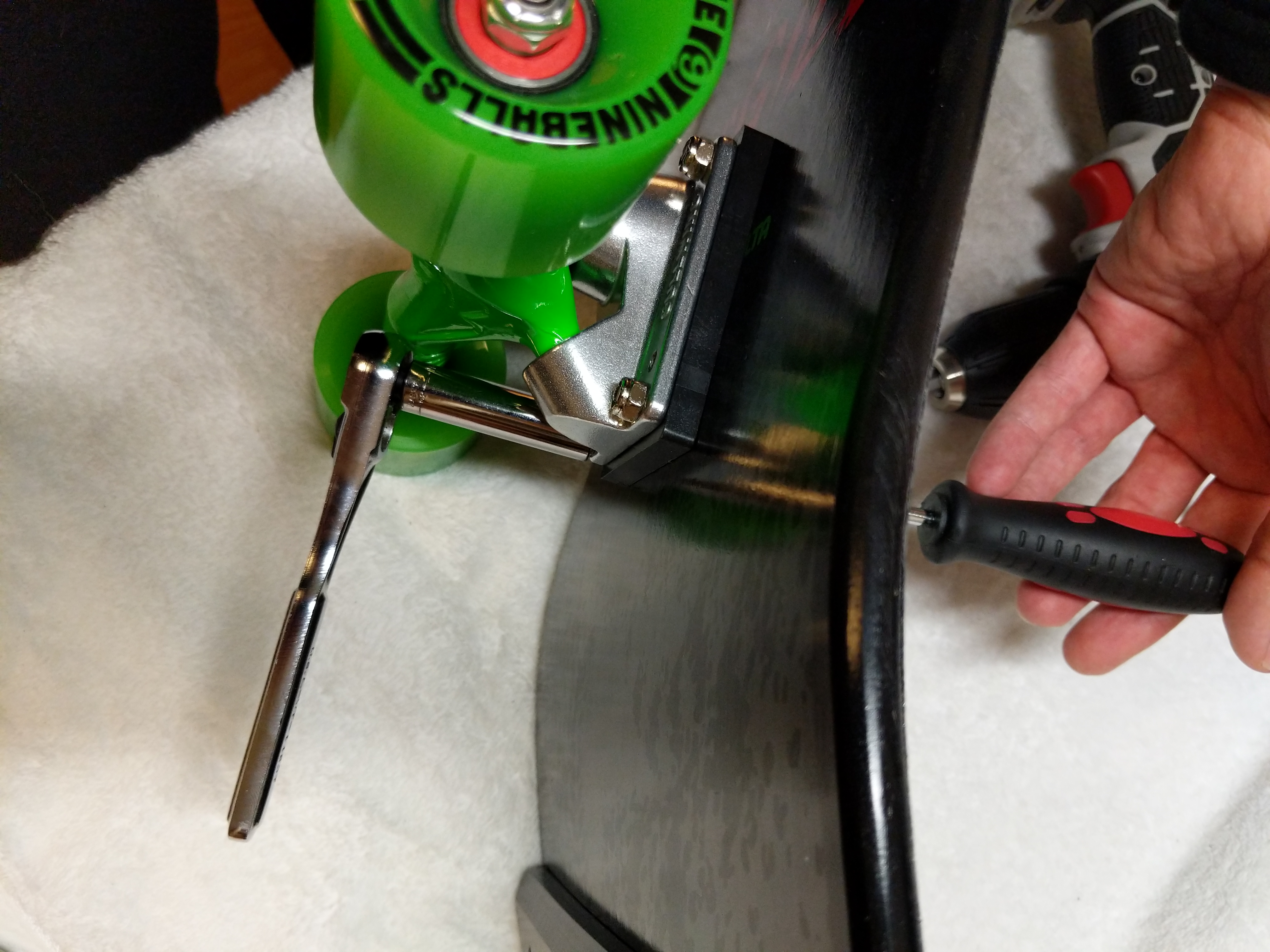
Next, I turned the skateboard on its side and mounted the trucks.
I hand threaded the four hardware nuts on each mounting bolt for each truck.
After confirming each nut was threaded correctly, I used the cordless drill to snug each bolt down to the nut and then hand tightened each bolt in an X-pattern until I was confident in each truck’s mounting to the skateboard deck.
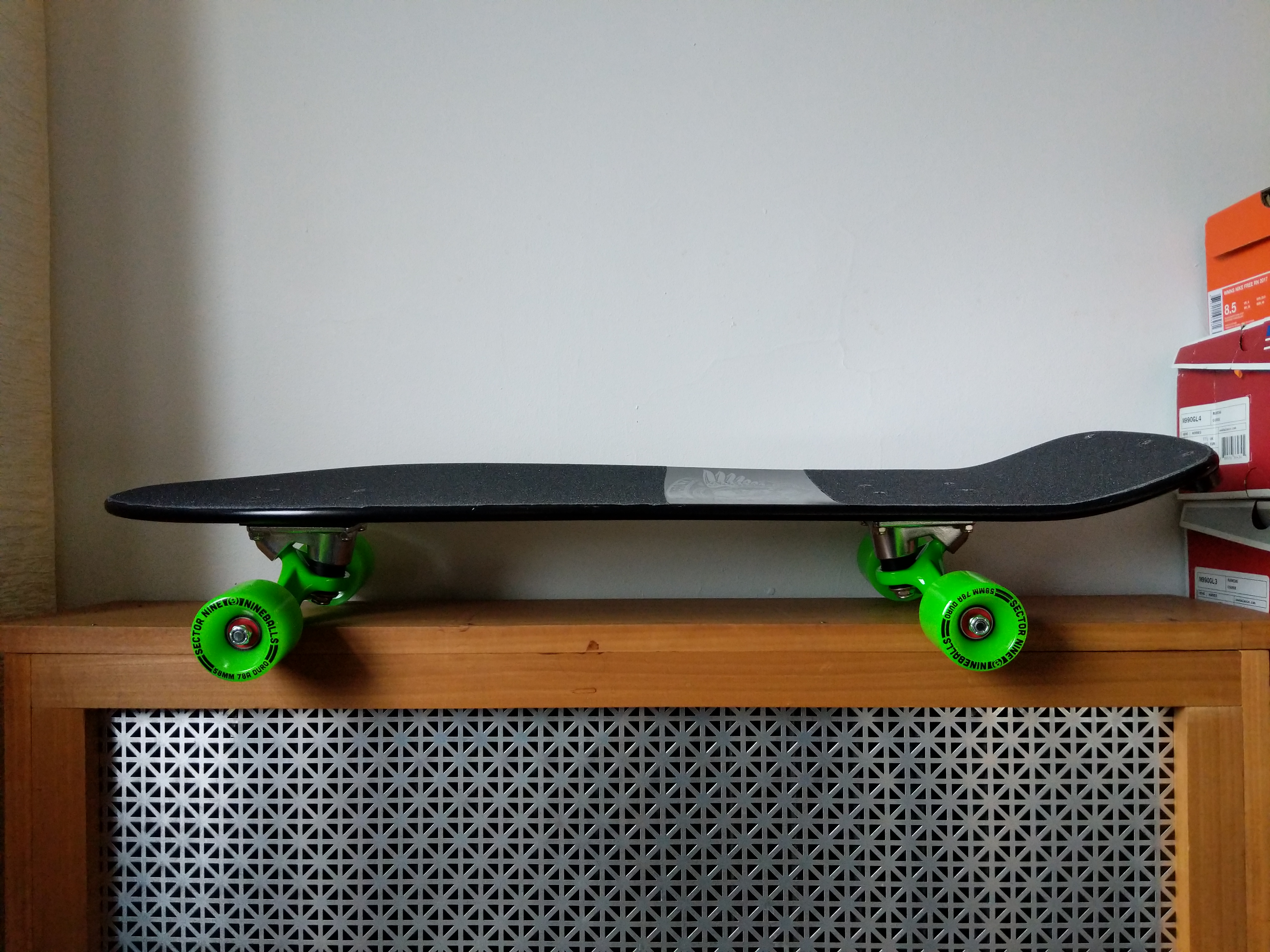
With the trucks mounted, I have a complete skateboard ready to take out and hit the streets with. The soft, larger wheels should be great for riding in my neighborhood. However, I have been looking at Powell-Peralta’s G-Slides, which I might get later.
I opted to cover the “Bones Brigade” name beneath the logo, because I wanted a little more grip on the tail section of the deck.
My original McGill had a nose kick while this late-80s re-issue does not. Nevertheless, I think this will be a fun skateboard to ride. Y asked me to wait until she returned from her trip to see her parents before I rode it in case I hurt myself. She’s back, but the weather isn’t superb, so I might content myself with daydreaming about riding my new skateboard until we can take it out together.
In all honesty, I have to remind myself that I can’t necessarily do the things I did when I was younger, or put another way, I can try to do the things that I used to do, but there will likely be more serious consequences. C’est la vie!
My cousin Ryan Cox is a longtime practitioner of a variety of martial arts including kung fu and tai chi. Ryan and his two older brothers–Ian and Jarret–grew up learning, sparring, and developing uncanny skill in hand-to-hand combat and weapons sparring. While Ryan and his brothers have developed rhizomic networks to enhance their abilities and pass on what they have learned to others, Ryan has went the most far afield when he traveled to Wudang Mountain to train with the kung fu monks who reside there.
Photo courtesy of Ryan Cox.
When we were younger, I remember myself being the one drawn to the Star Wars mythos more than anyone else in my family, but now Ryan tells me that he was always interested in the Jedi, their mystique, and their lightsabers. In more recent years, he has learned a lot of the backstory of the Star Wars universe from books and video games. His knowledge in those realms far outstrips my own.
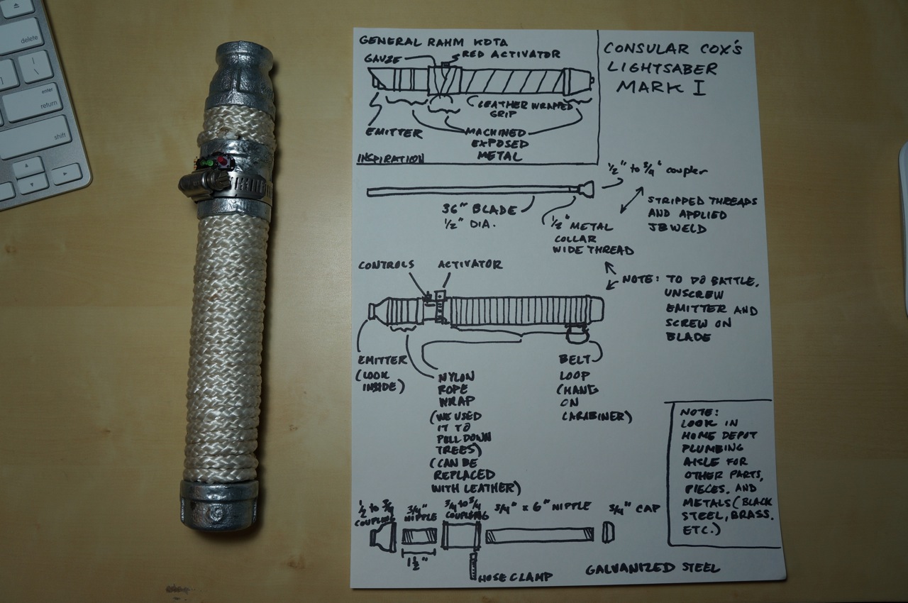
So, I was intrigued when he began talking with me about building his own lightsaber for demonstrating his swordmanship and possibly sparring if the “blade” were strong enough to withstand strikes. The guide that follows illustrates the first lightsaber that I built for Ryan in the fashion of General Rahm Kota’s. I used off-the-shelf parts easily obtained at Home Depot or any hardware store. Since I built this lightsaber, Ryan has modified it more, and I have built two lightsabers for myself–one that resembles Luke Skywalker’s Return of the Jedi lightsaber and one that resembles Darth Maul’s The Phantom Menace double bladed lightsaber. This guide focuses on Ryan’s “Mark I” lightsaber.
Pedagogically, I promote the idea that haptics, building, and making are integral parts to any kind of education. We are embodied beings who do things physically in the world–whether it be in real life or online. I enjoy building things in my own time as another way to think about things–in this case, Star Wars, science fiction, Jedi mythos, world building, canon vs. noncanon, and design considerations: rhetoric of technology, aesthetics, practicality, etc. In Ryan’s case, haptics, proprioception, and movement are integral to his learning and lived experience. I am looking forward to learning from him with this artifact that I designed and built. The modes are the same–physicality, materiality, and haptics–but our efforts converge from different directions for a kind of haptic, learning synergy.
I began the project by assembling the parts that I needed for creating the lightsaber’s hilt and belt clip. I carried an image of Rahm Kota’s lightsaber on my iPhone and went to the plumbing aisle of my local Home Depot.
These parts included:
6″ x 3/4″ galvanized steel pipe
3/4″ coupling
Two 3/4″ to 1/2″ coupling (one for display and one for sparring with permanently installed “blade”–these two couplings are interchangeable)
“Close” 3/4″ pipe (approximately 1 1/2″ long)
3/4″ cap
D-ring
Carabiner
Hose clamps
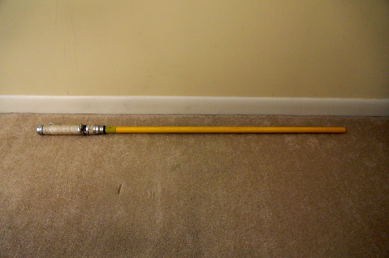
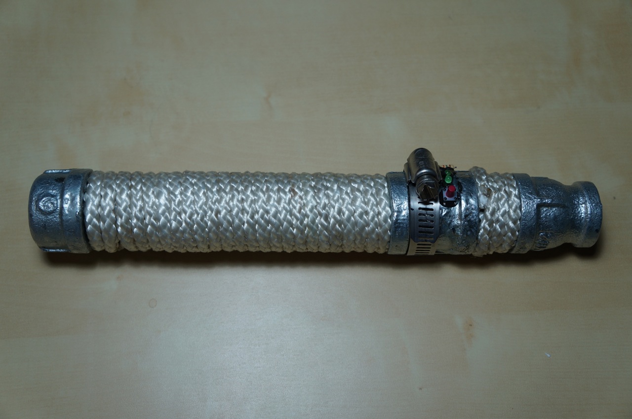
Roughly, these parts are assembled to create the lightsaber:
Other parts that I used for this build include:
1/4″ white nylon rope (grip wrap)
36″ x 1/2″ oak dowel rod (scrapped due to paint problem)
48″ x 1/2″ paint brush rod (cut to 36″ and replaced the oak dowel rod)
Doorbell button assembly (for parts)
80mm computer case fan (for electromagnet assembly)
JB Weld
Rustoleum Florescent Yellow Paint
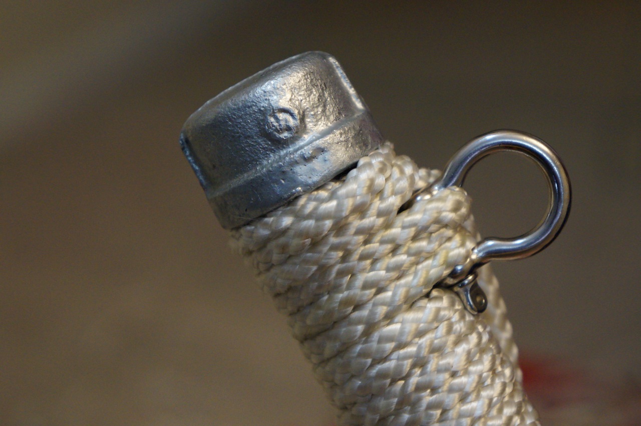
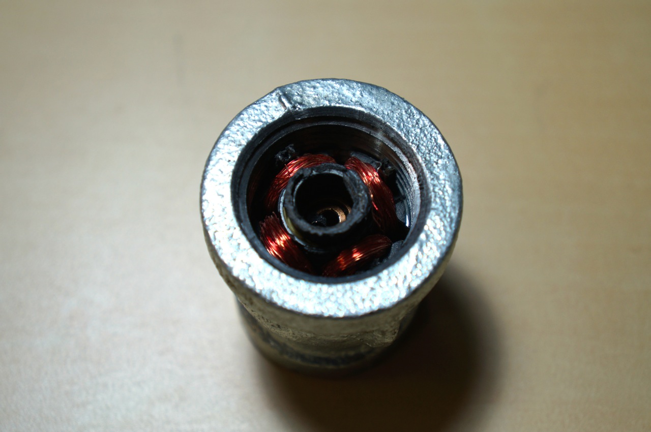
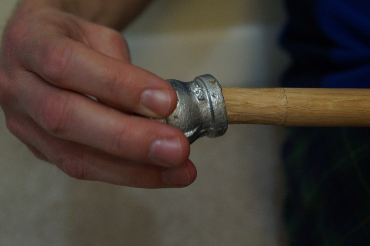
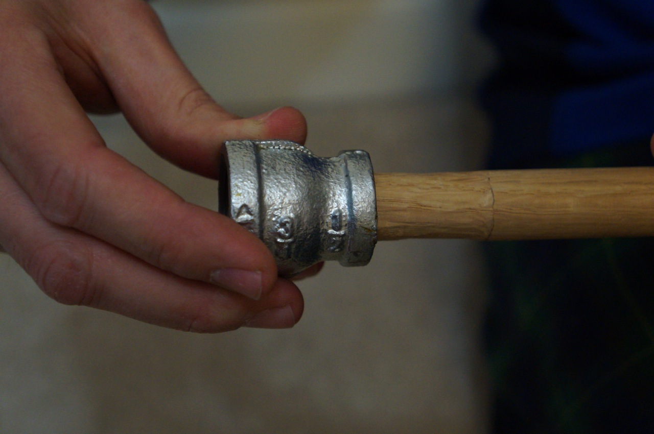
To create the lightsaber’s handle, I screwed all of the handle components together except for the 3/4″ to 1/2″ coupling like this: 3/4″ cap | 6″ x 3/4″ pipe | 3/4″ to 3/4″ coupling | 3/4″ close pipe.
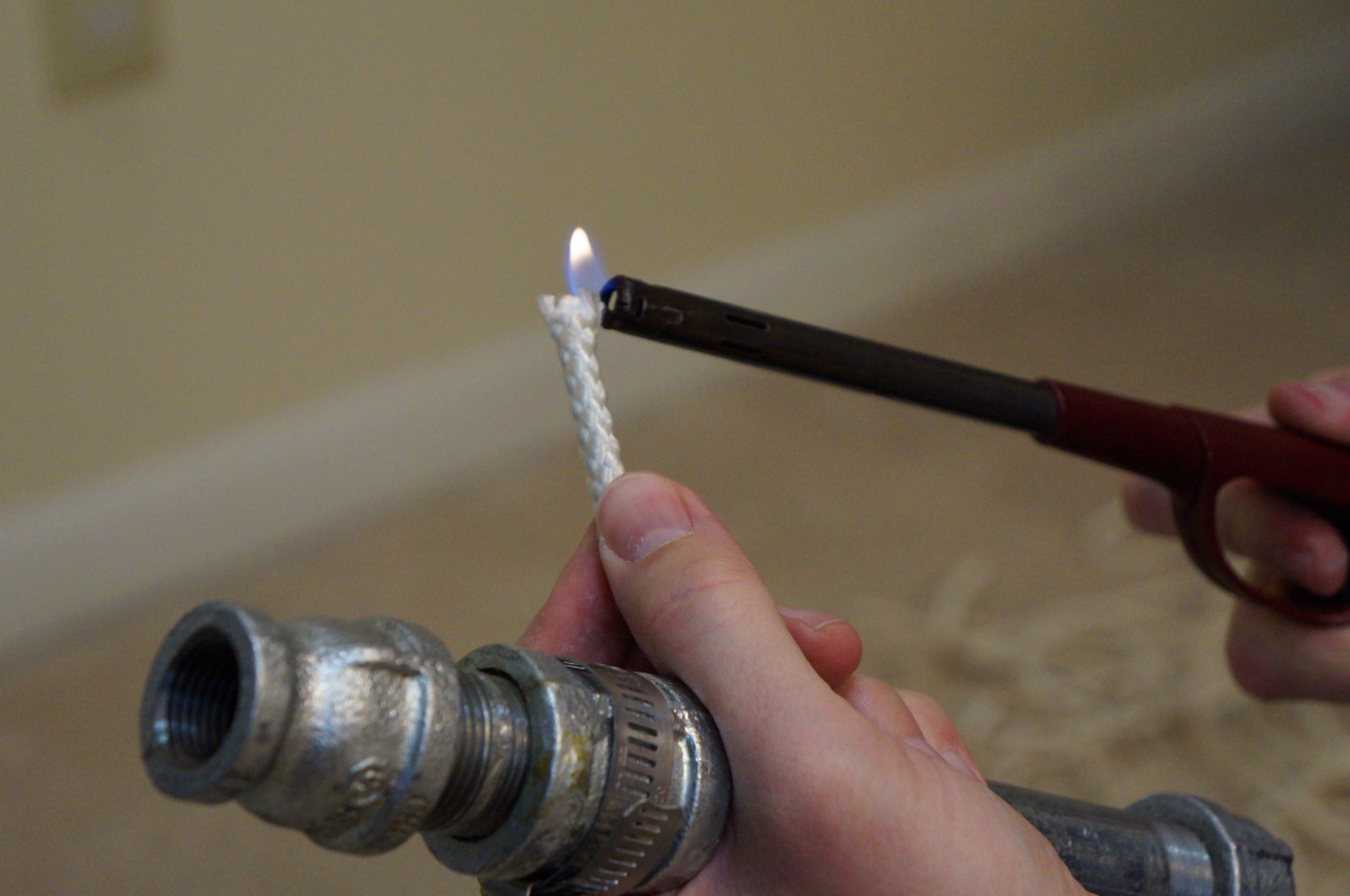
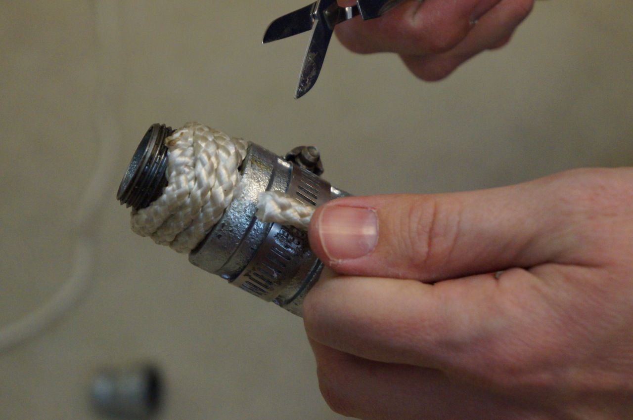
Then, I prepared the nylon rope to create the grip on the two pipe sections (6″ pipe and close pipe) by burning frayed ends to melt the nylon.
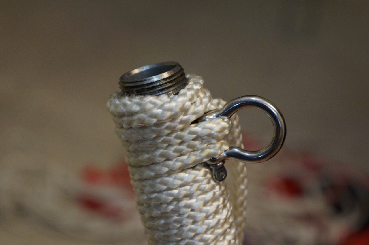
Beginning at the business-end of the lightsaber, I tucked a small piece of rope under the first wrap against the 3/4″ coupling to hold the rope in place and prevent unraveling.
At the top end, close to where the 3/4″ to 1/2″ coupling (or lightsaber emitter/business end), I created a loop with the rope under the last wrap, which I ran the last wrap through and pulled into the wrap, which hid the end of the rope under the wrap.
I cut the loose ends. Beginning on the other side of the 3/4″ coupling, I repeated these steps with the longer wrap of the 6″ pipe section. First, a small piece under the first wrap.
I pulled the rope tight around the pipe and pushed each wrap down to keep the grip as tight as possible.
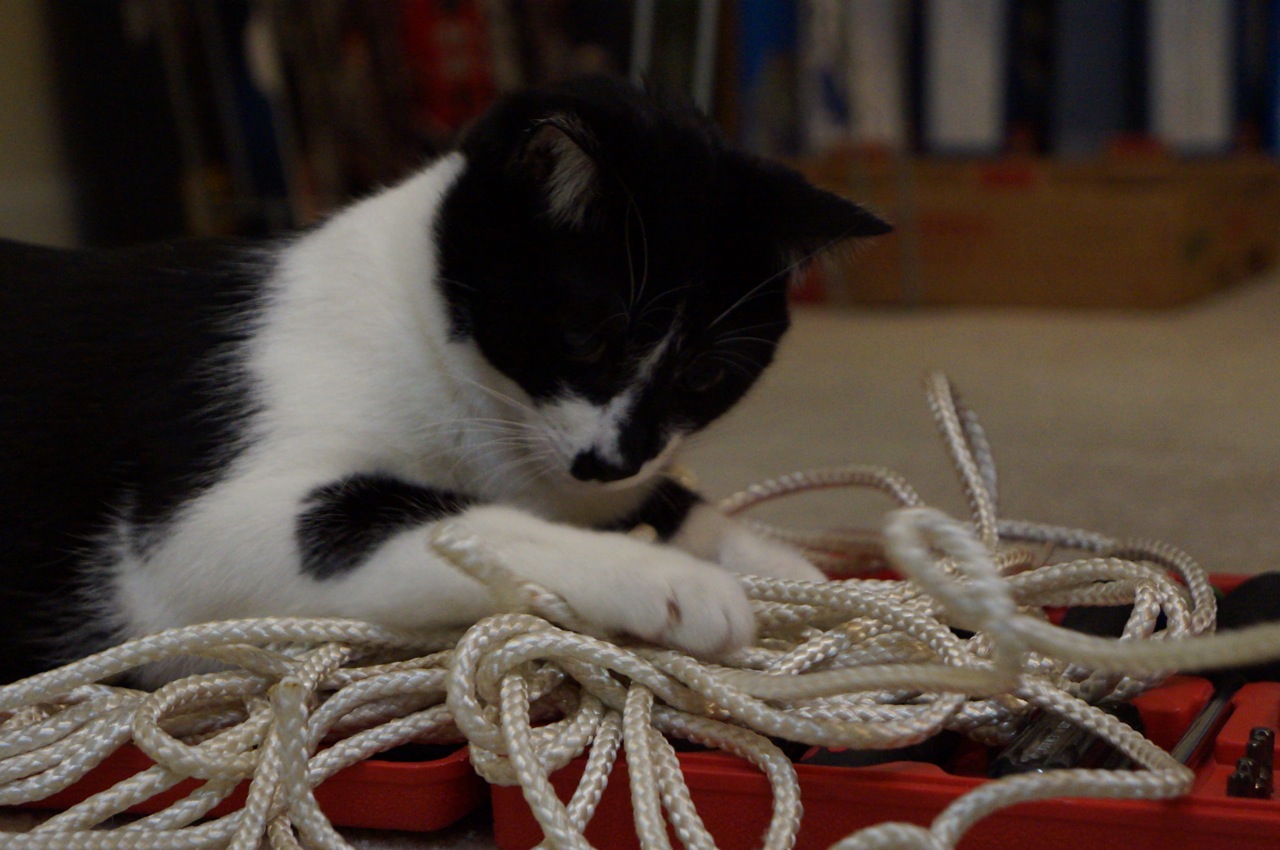
Mose tried to help with the process as much as possible.
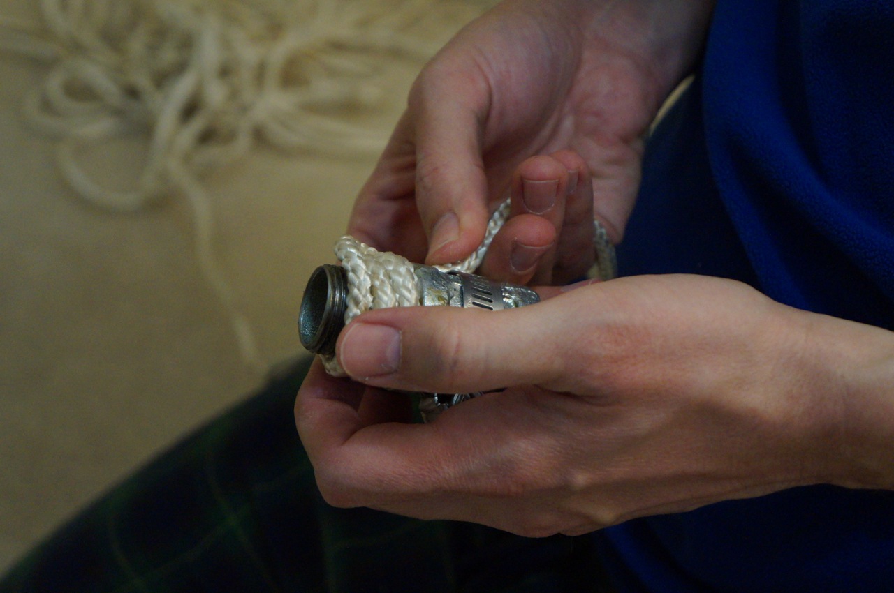
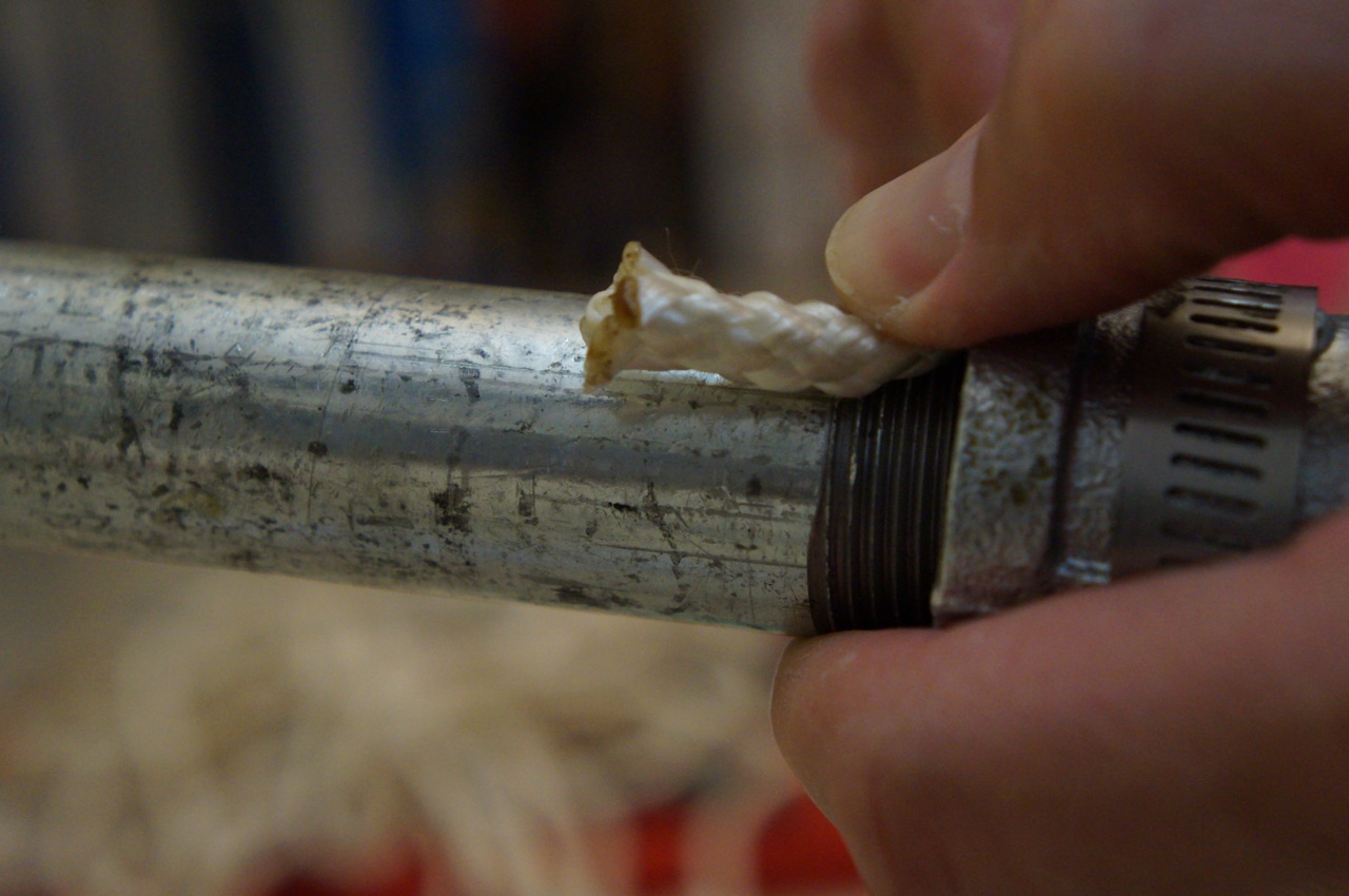
At the end of the 6″ long pipe, close to where the end cap goes, I placed the D-Ring and ran the rope through its eye to connect it to the handle.
As in the shorter section wrap, I created a loop and pulled the end of the rope through and under the last lines of wrap to hide the end and prevent the grip from unraveling.
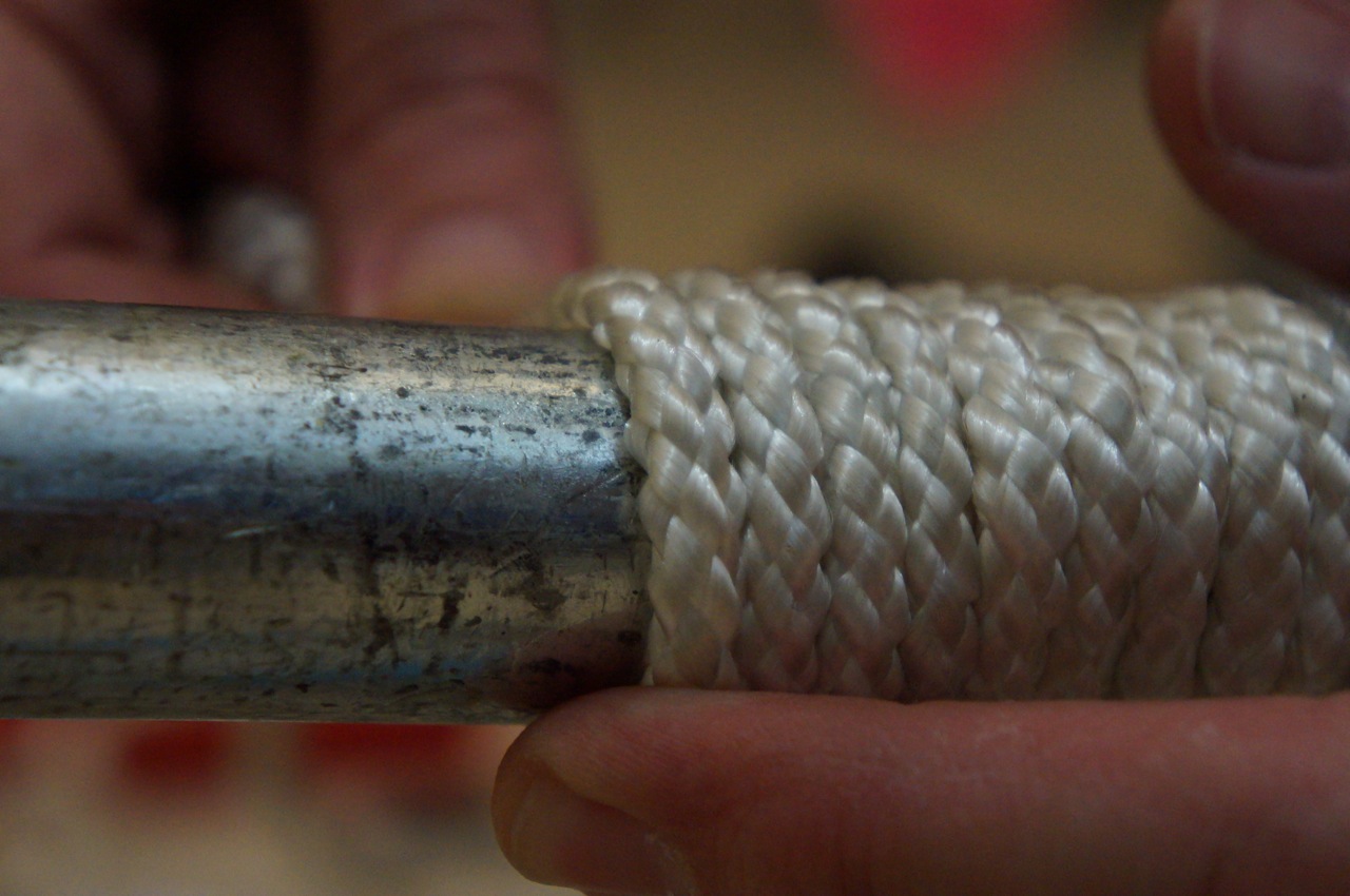
Finally, I installed the cap. Before doing this, I wrapped the grip higher than necessary so that the the cap would compress the wrap when tightly screwed onto the 6″ pipe.
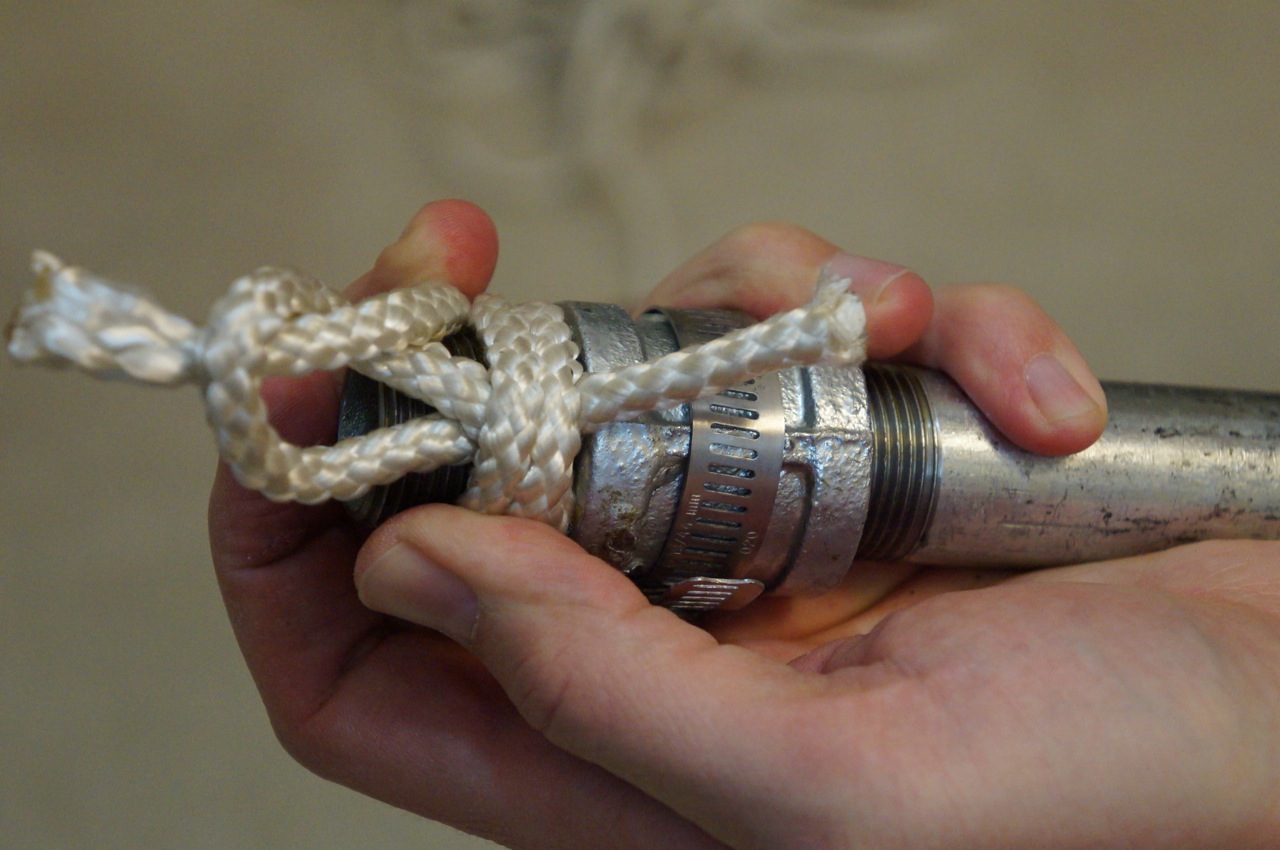
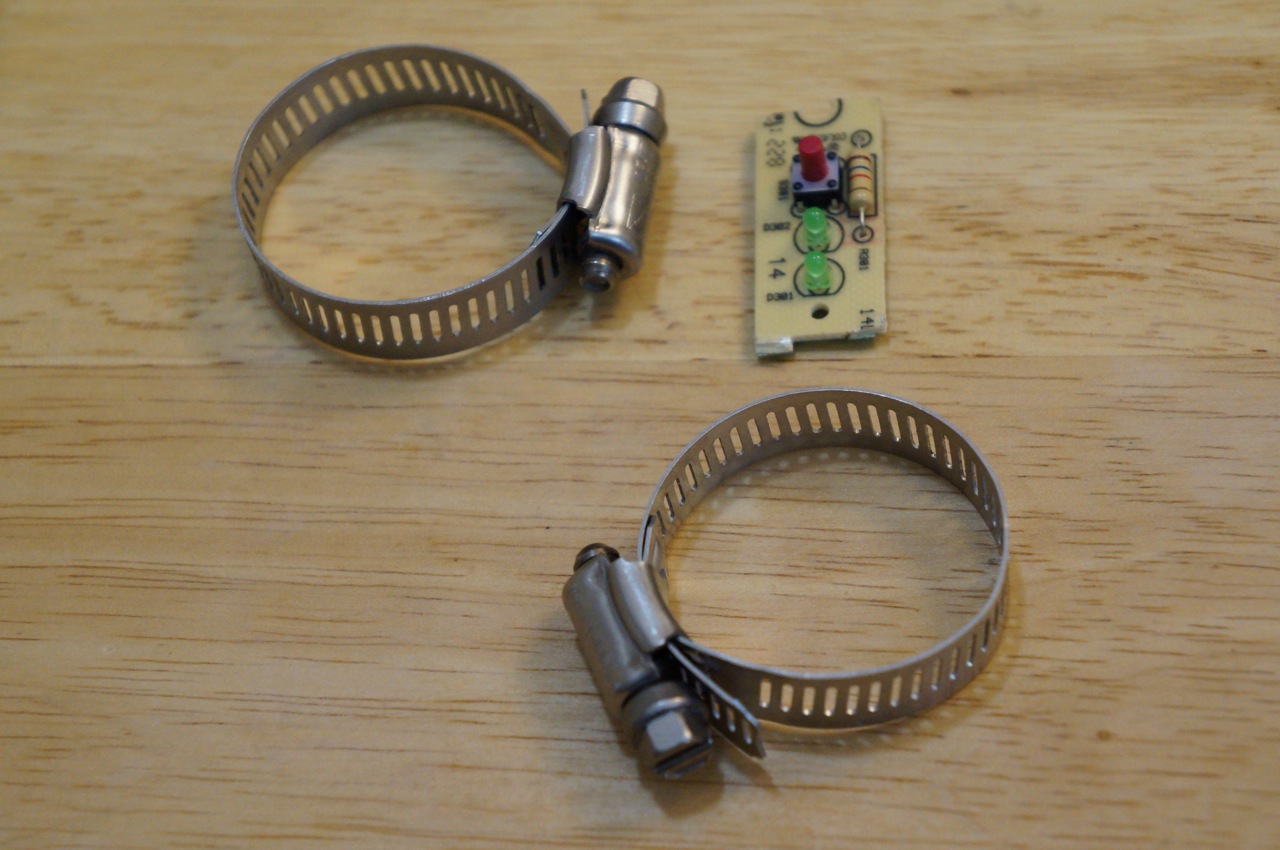
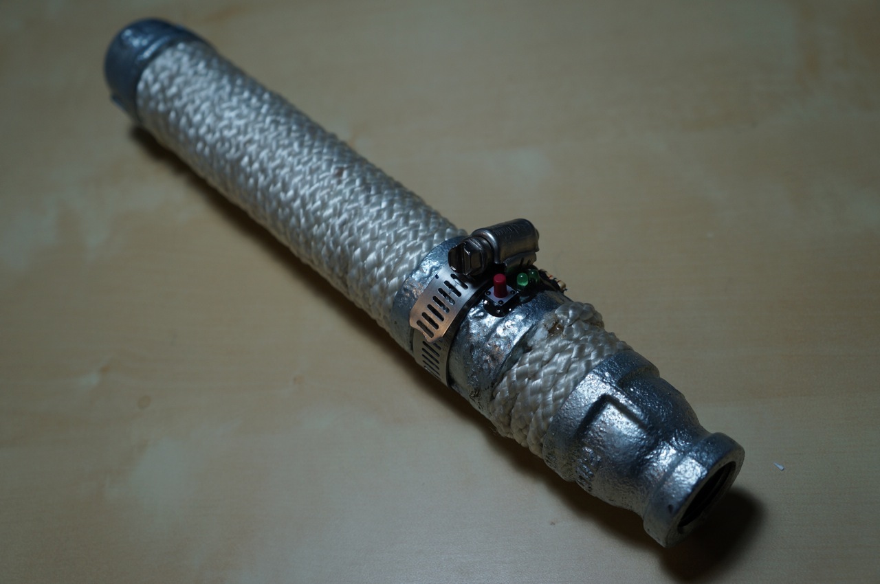
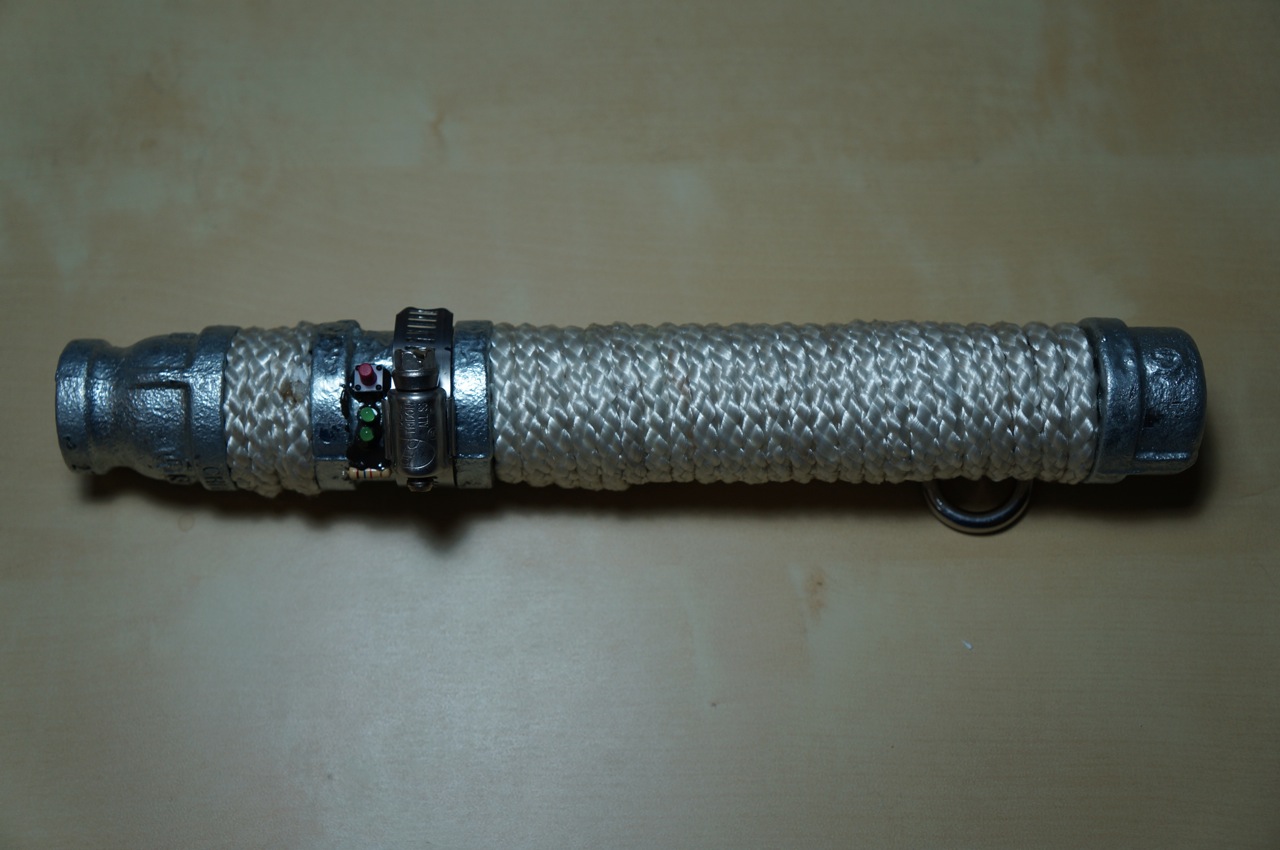
Since Ryan would likely bang his lightsaber when sparring, I wanted to make it as practical as possible while giving it a technological appearance. First, I tried attaching a circuit board from an average doorbell button with two hose clamps.
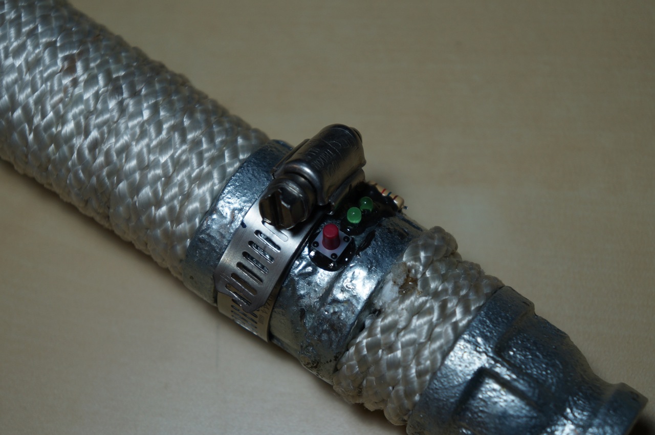
While I thought this fit the rugged look that Ryan might like for his lightsaber, I thought that it would be more practical to use only one hose clamp and affix the doorbell components with JB Weld after removing them from the circuit board.
I liked this configuration best. The hose clamp protects the switch, lights (non-functional), and resistor.
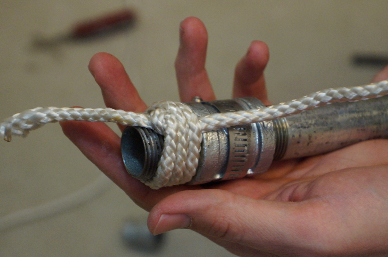
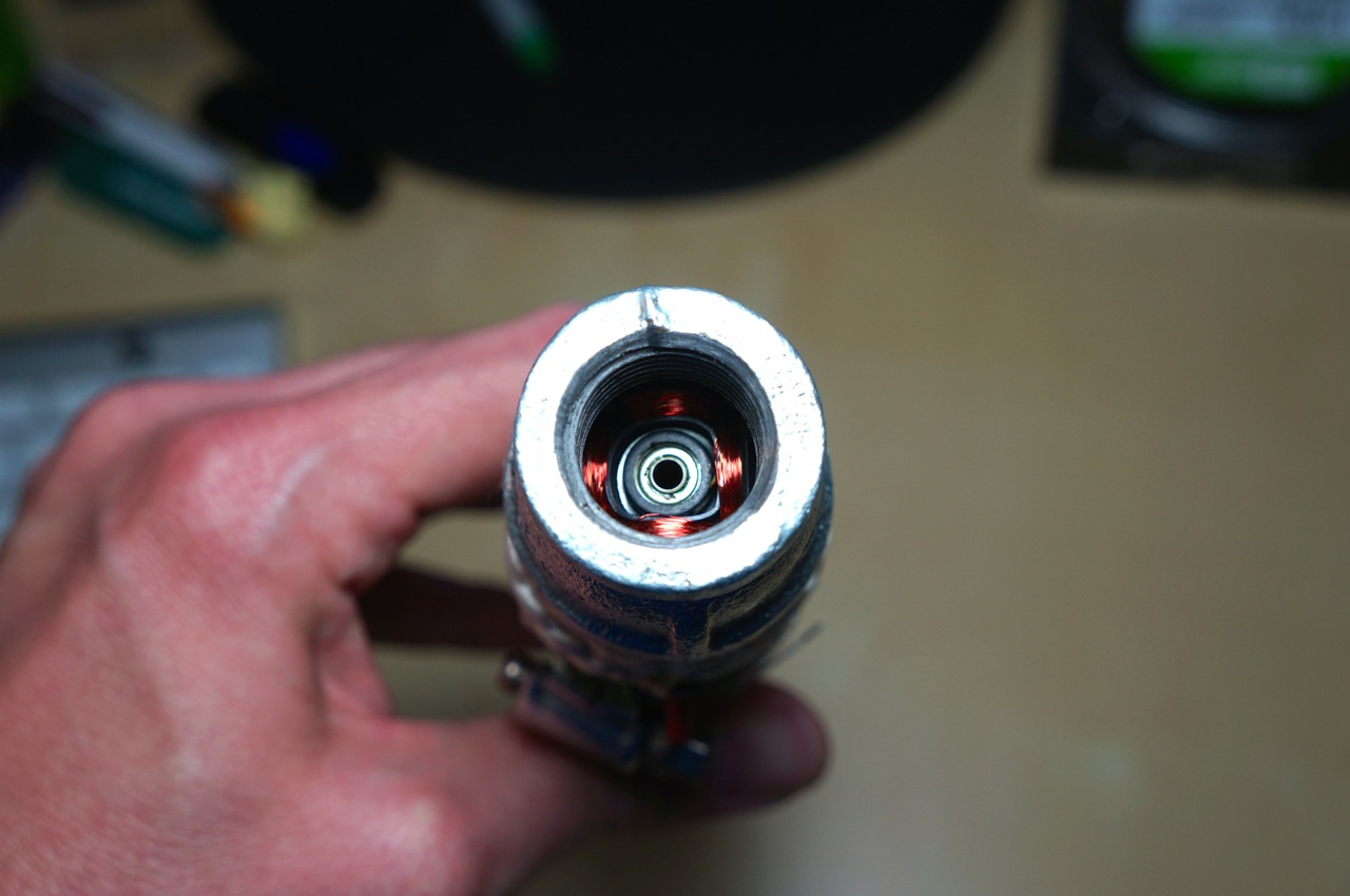
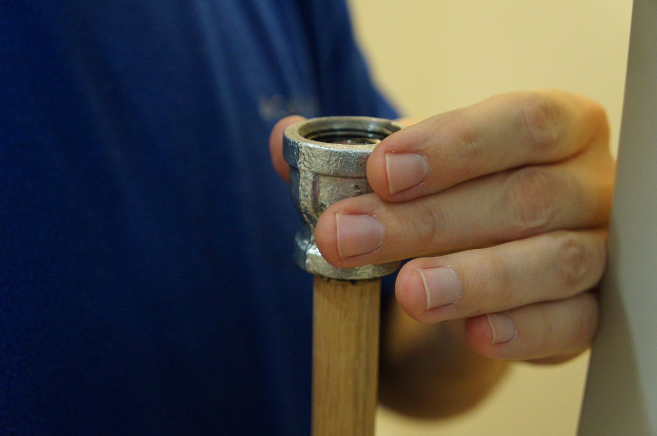
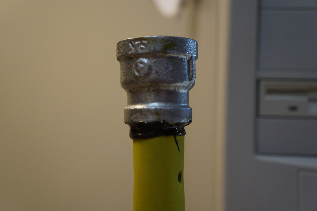
Next, I wanted the display emitter on the deactivated lightsaber (3/4″ to 1/2″ coupling) to look “realistic,” so I pulled the electromagnet from an 80″ computer fan, crushed it with my channelocks, and inserted it into the 3/4″ end of the 3/4″ to 1/2″ coupling. Repurposing the electromagnet draws on a visual/physical rhetoric of technology in the same way that movie props and set design use this for world building, extrapolating, and establishing plausibility.
The next phase of the lightsaber build involved the other sparring emitter. I needed to rigidly attach a wooden blade to the second 3/4″ to 1/2″ coupling in the 1/2″ end of the coupling and paint it to match the yellow blade color that Ryan sought (signifying the Consular Jedi).
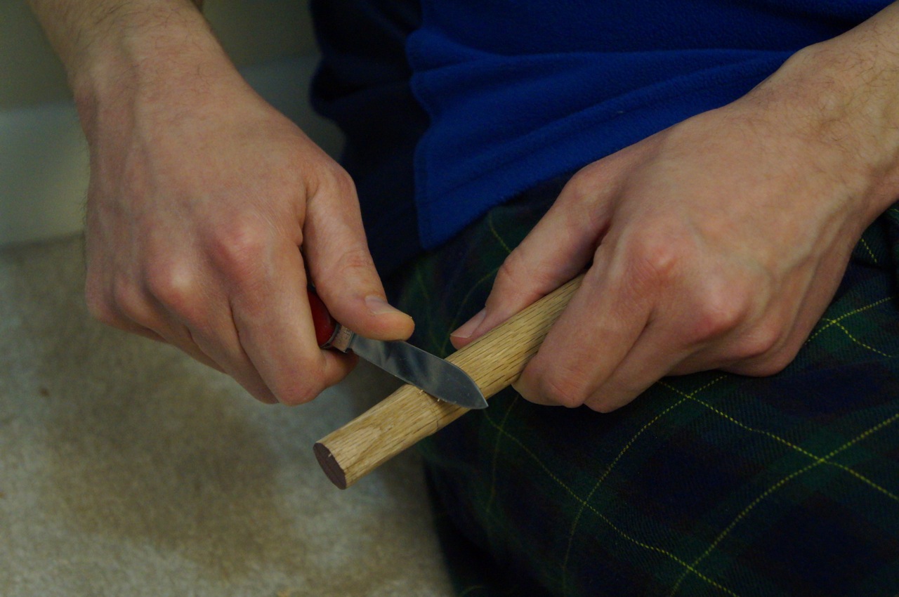
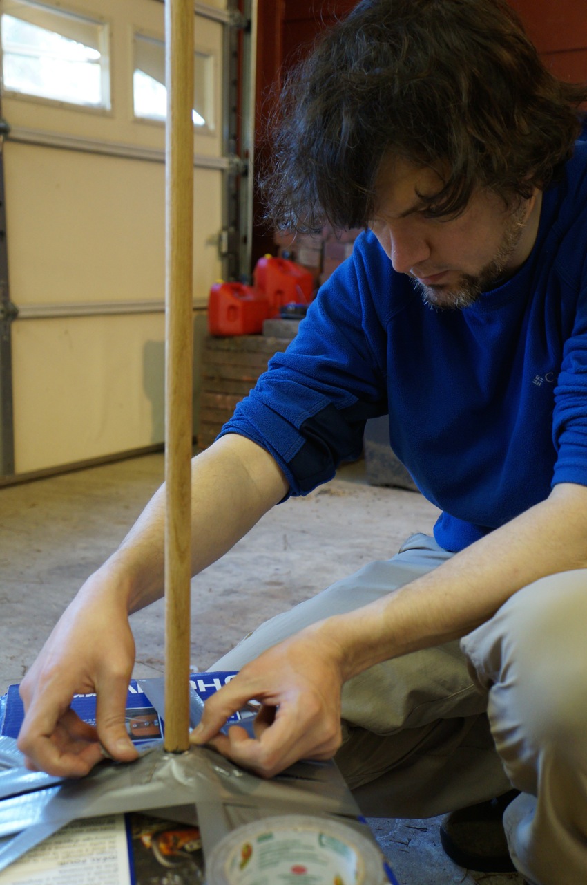
I began by taking an oak dowel rod and whittling one end enough to screw it into the 1/2″ end of the 3/4″ to 1/2″ coupling.
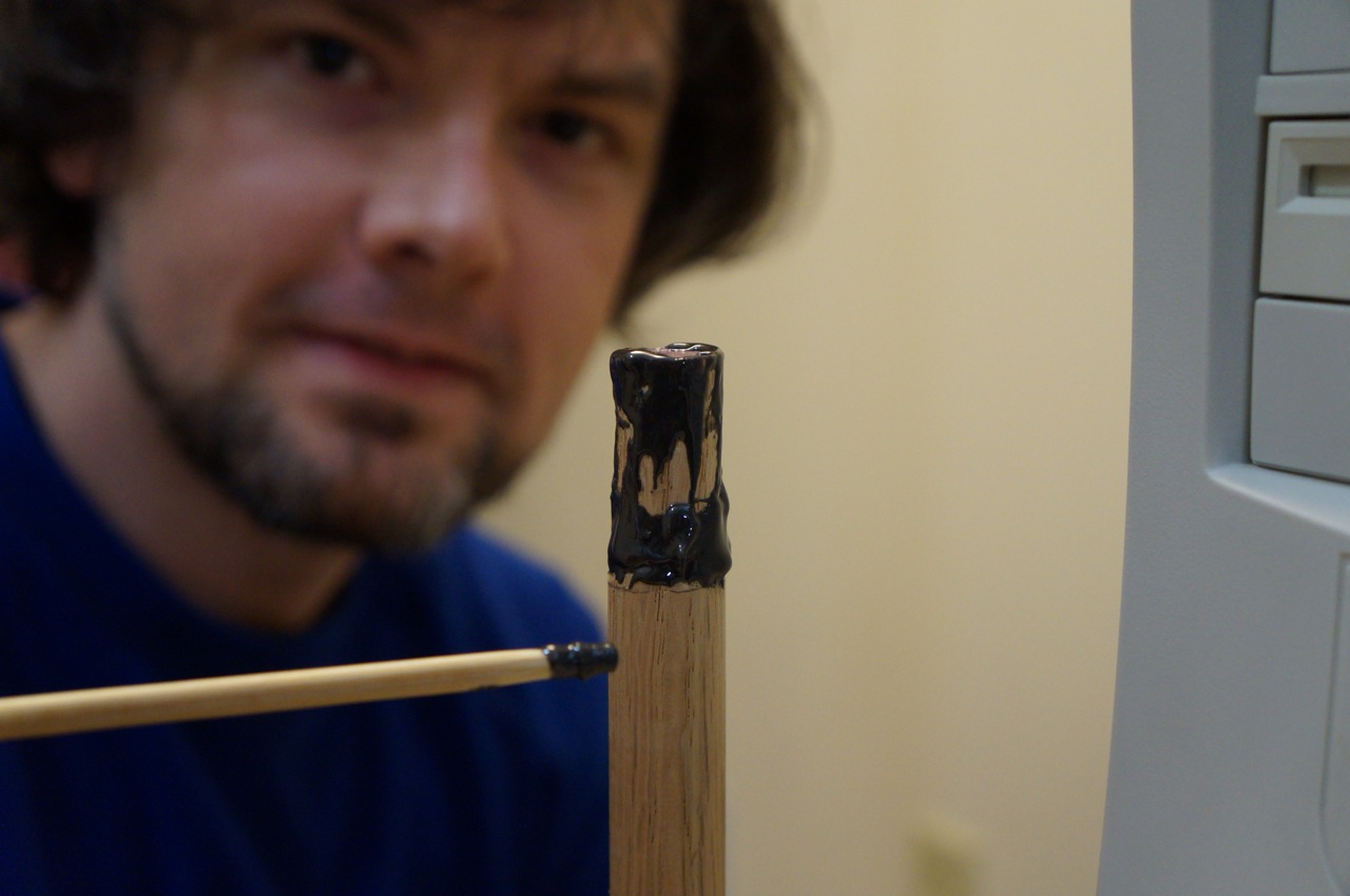
Then, I used JB Weld to permanently connect the coupling to the dowel rod.
I had to make sure that I did not put too much JB Weld on the tip closest to the 3/4″ pipe thread, which screw into the “close” end of the lightsaber when the blade needs to be drawn.
I made sure that it was centered and straight.
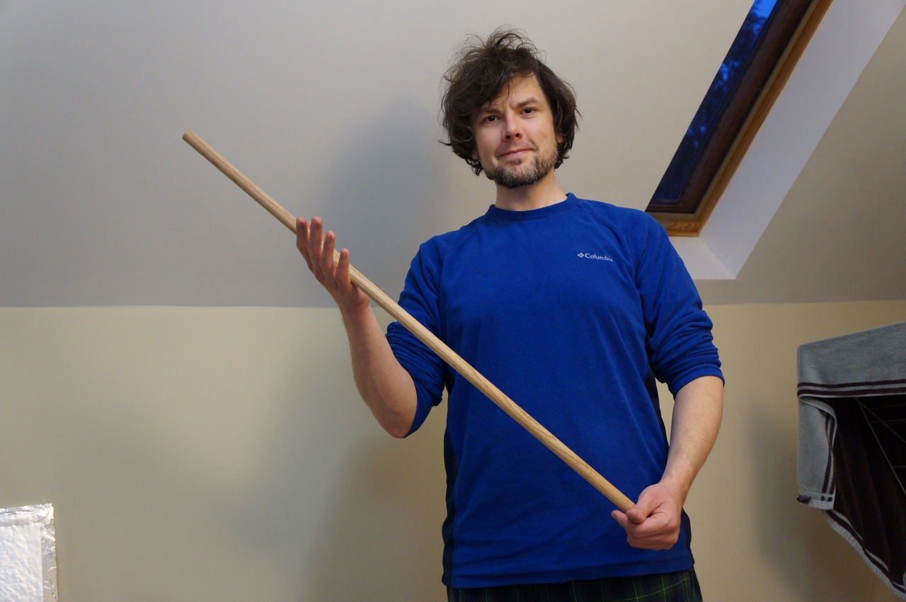
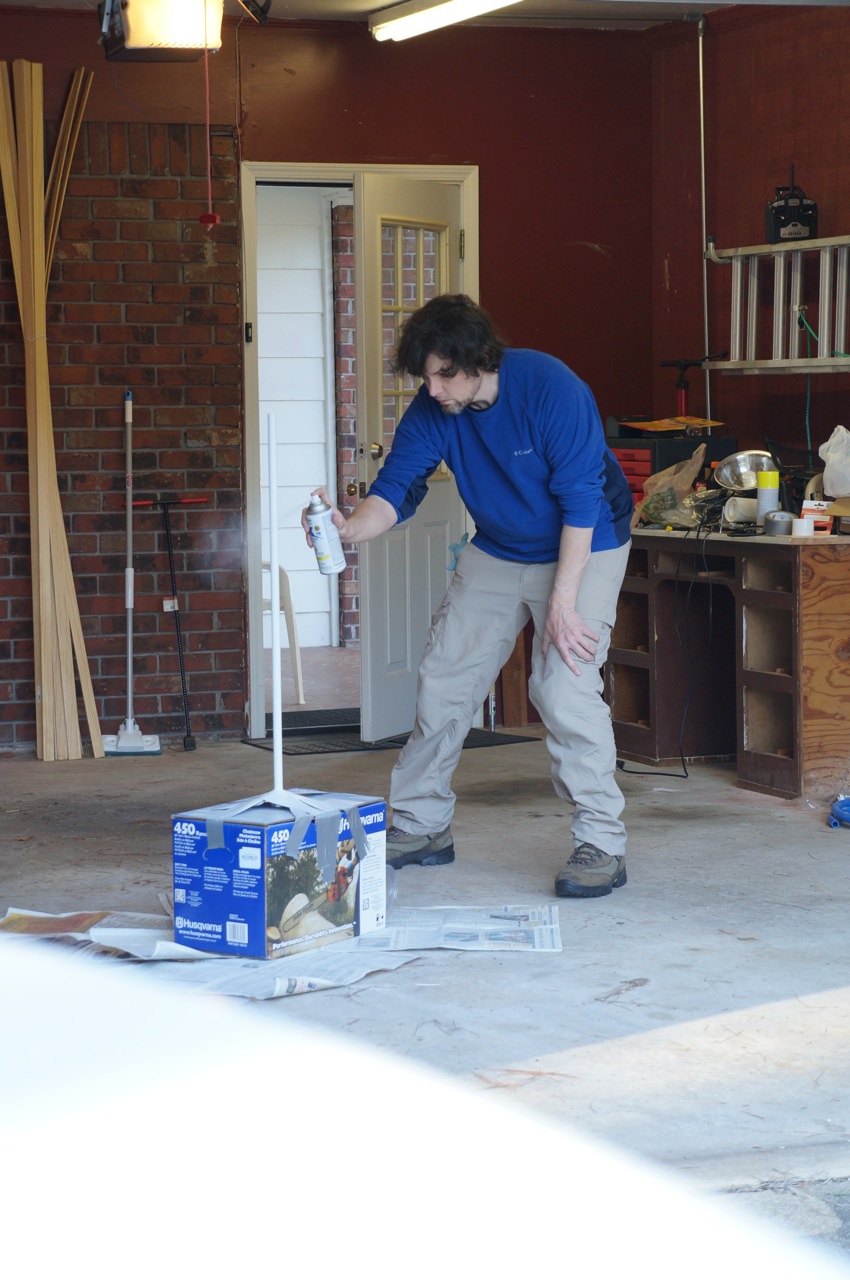
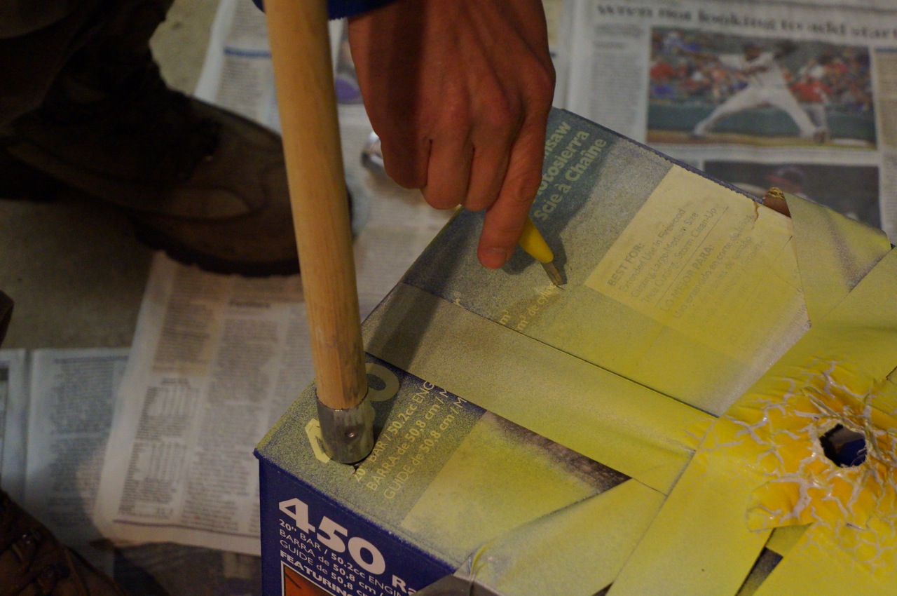
Finally, I painted the dowel rod above the coupling with a primer and then with the florescent yellow.
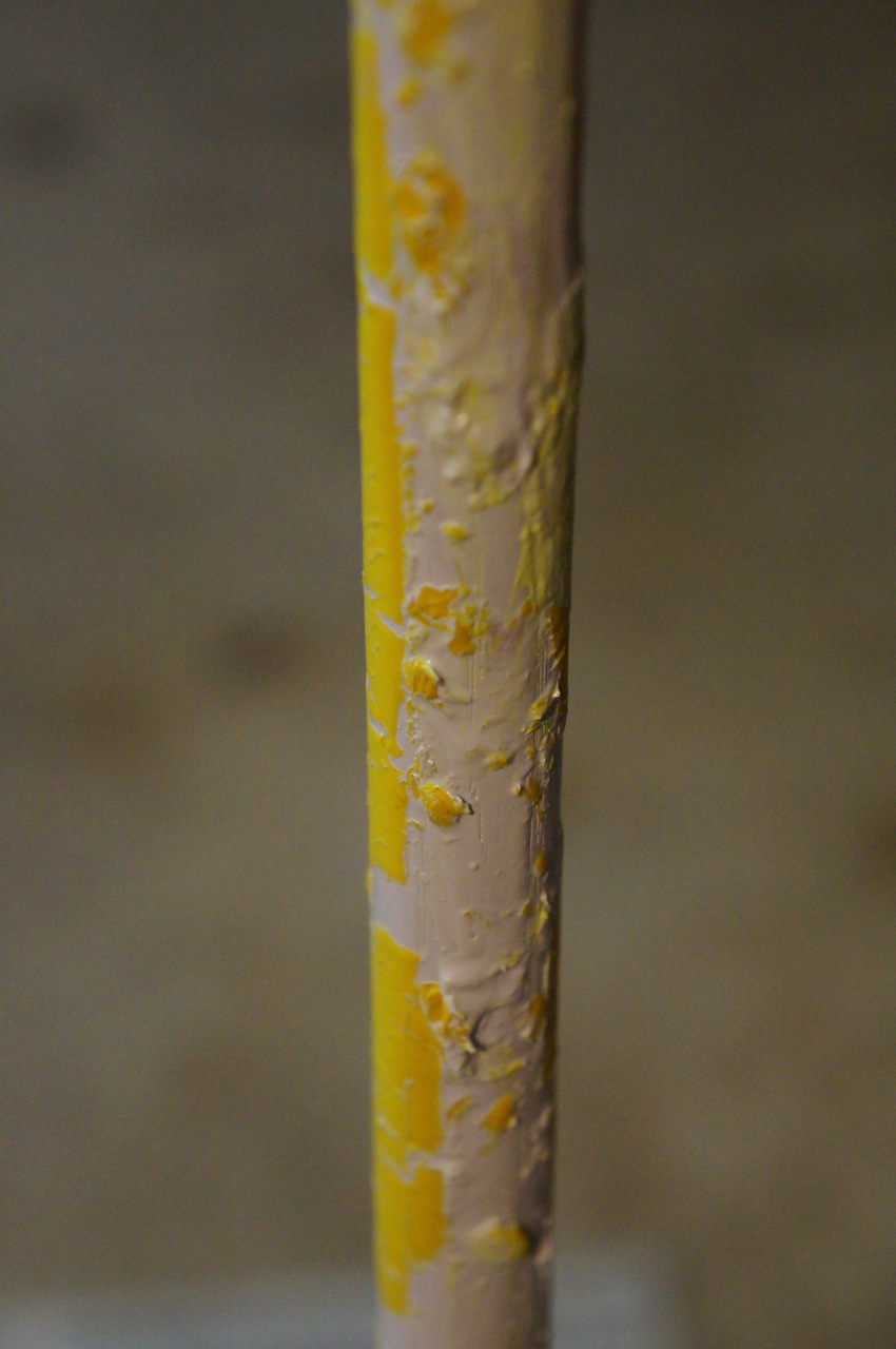
Unfortunately, I misread the spray paint cans and ended up with a mess when the florescent yellow would not stick to the dried primer (I mistakenly picked up white primer + paint instead of simply primer).
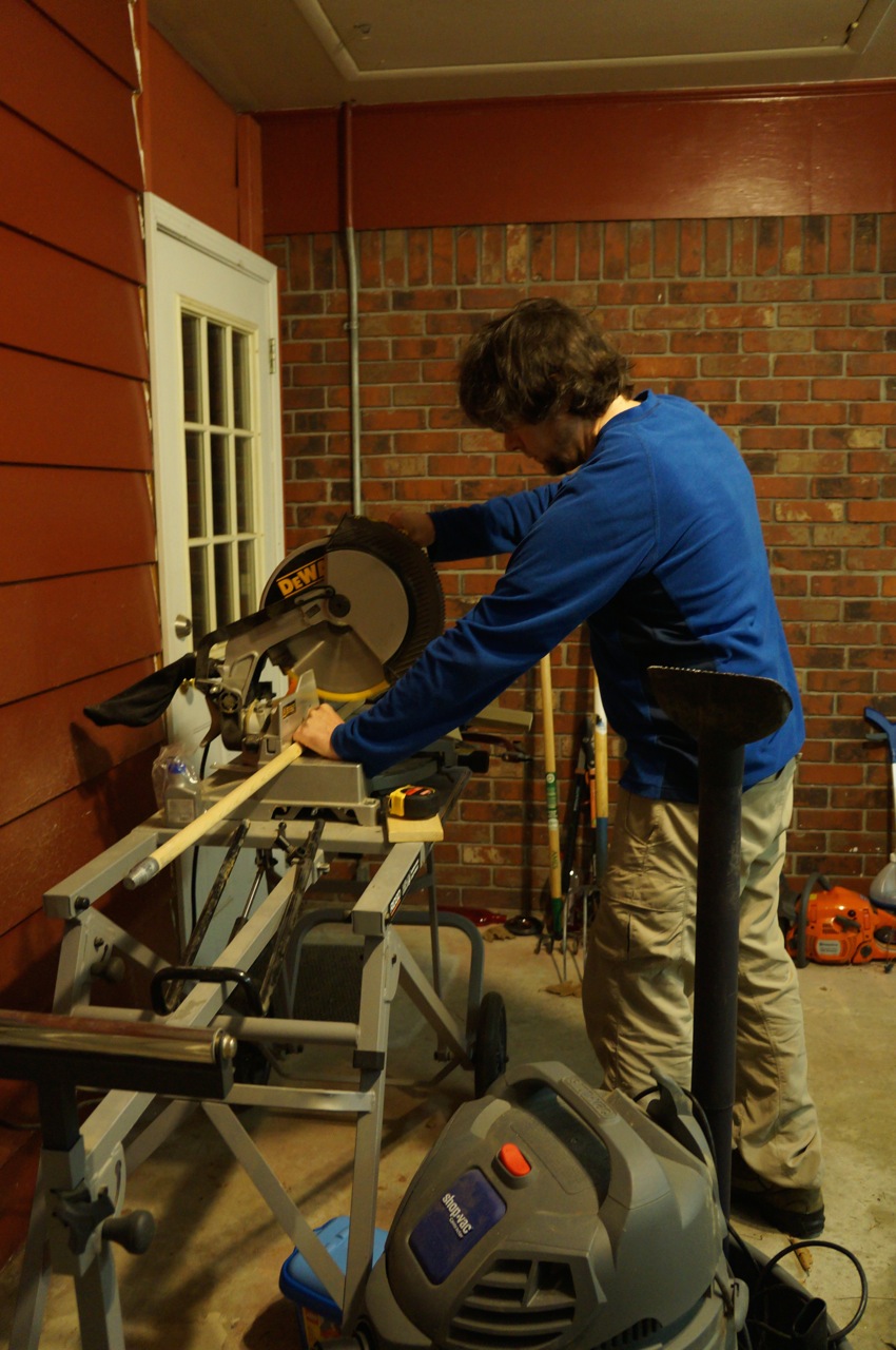
Luckily, I had a paint brush handle in the garage that was long enough to serve the same purpose even if it might be made out of pine instead of oak.
I cut the paint brush handle down to 36″.
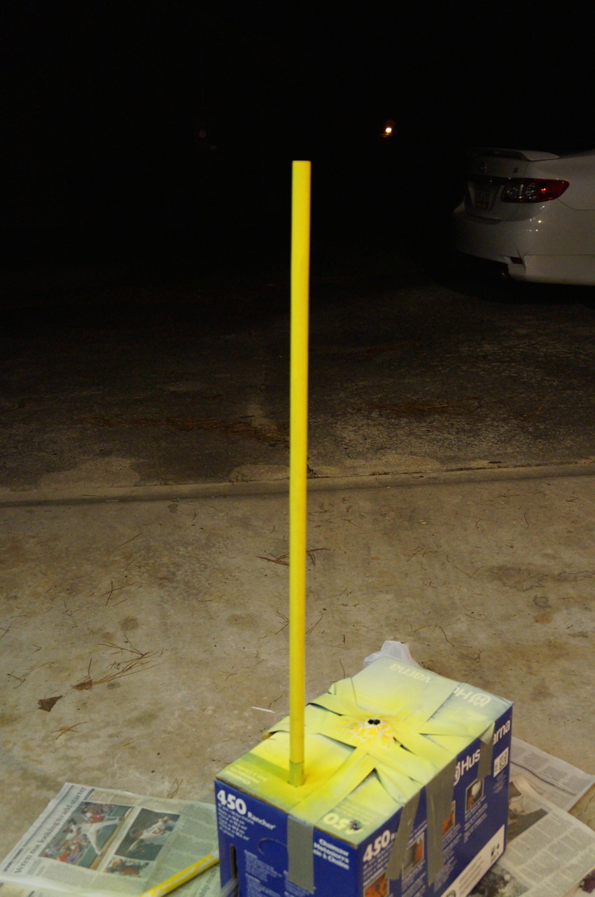
Set it up for painting with the remaining florescent yellow paint.
Many coats later, it was a bright yellow befitting a Consular Jedi!
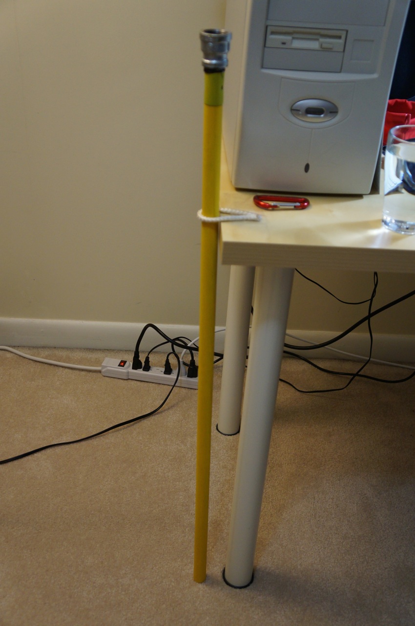
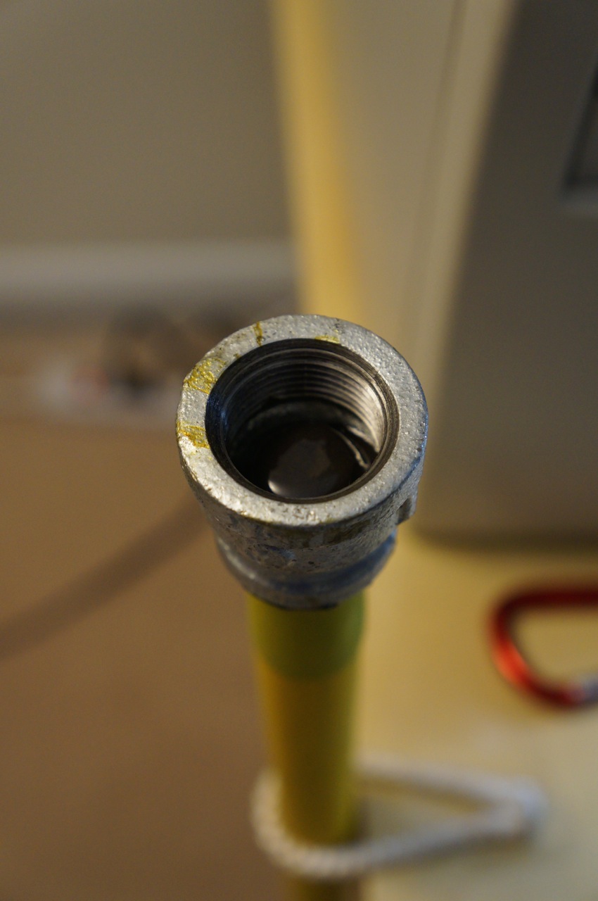
After the paint dried, I screwed the metal end of the brush into another 3/4″ to 1/2″ coupling and bonded the blade to the coupling with JB Weld.
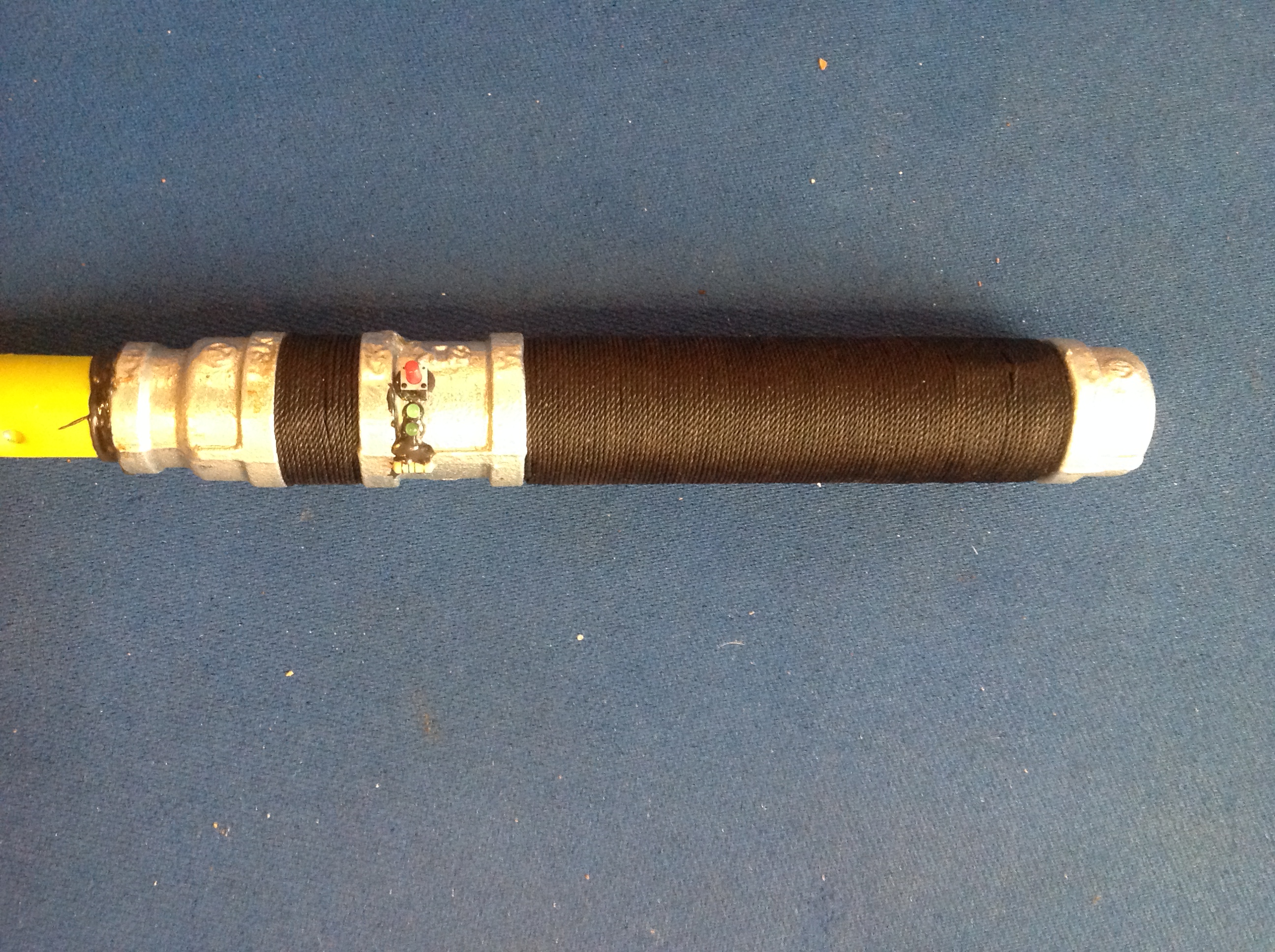
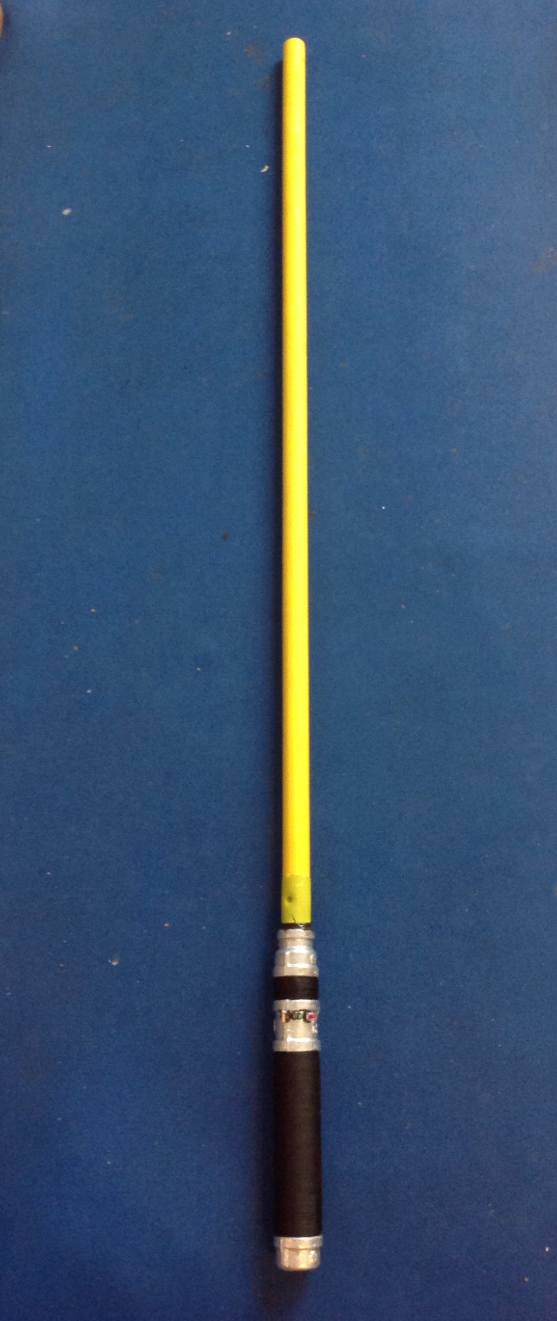
After everything had dried, I mated the blade with the lightsaber handle.
I was happy with the outcome of the lightsaber in deactivated mode, too.
I gave the lightsaber to Ryan as a birthday present. I included this explanatory diagram that explains how the saber is more than simply parts (e.g., the rope is from the same bundle that Ryan and I used when we cut trees down in my yard last year).
Since I build this lightsaber, Ryan removed the nylon rope grip and improved it with three layers of bank line or tarred twine. The result is quite impressive aesthetically and practically!
Photo courtesy of Ryan Cox.
Photo courtesy of Ryan Cox.
I will post future posts on the lightsabers that I have built for myself and examples of our sparring (when we have the time for Ryan to teach me some things).
UPDATE: Readers asked me to post photos of my other lightsabers–one inspired by Luke Skywalker’s lightsaber in Return of the Jedi and Darth Maul’s double-bladed lightsaber from The Phantom Menace. When I built these sabers for myself, I didn’t take as many photos of the process as in the lightsaber above for Ryan, but these photos should illustrate the basics of how to build similar DIY lightsabers.
Luke Skywalker ROTJ Lightsaber and Stand
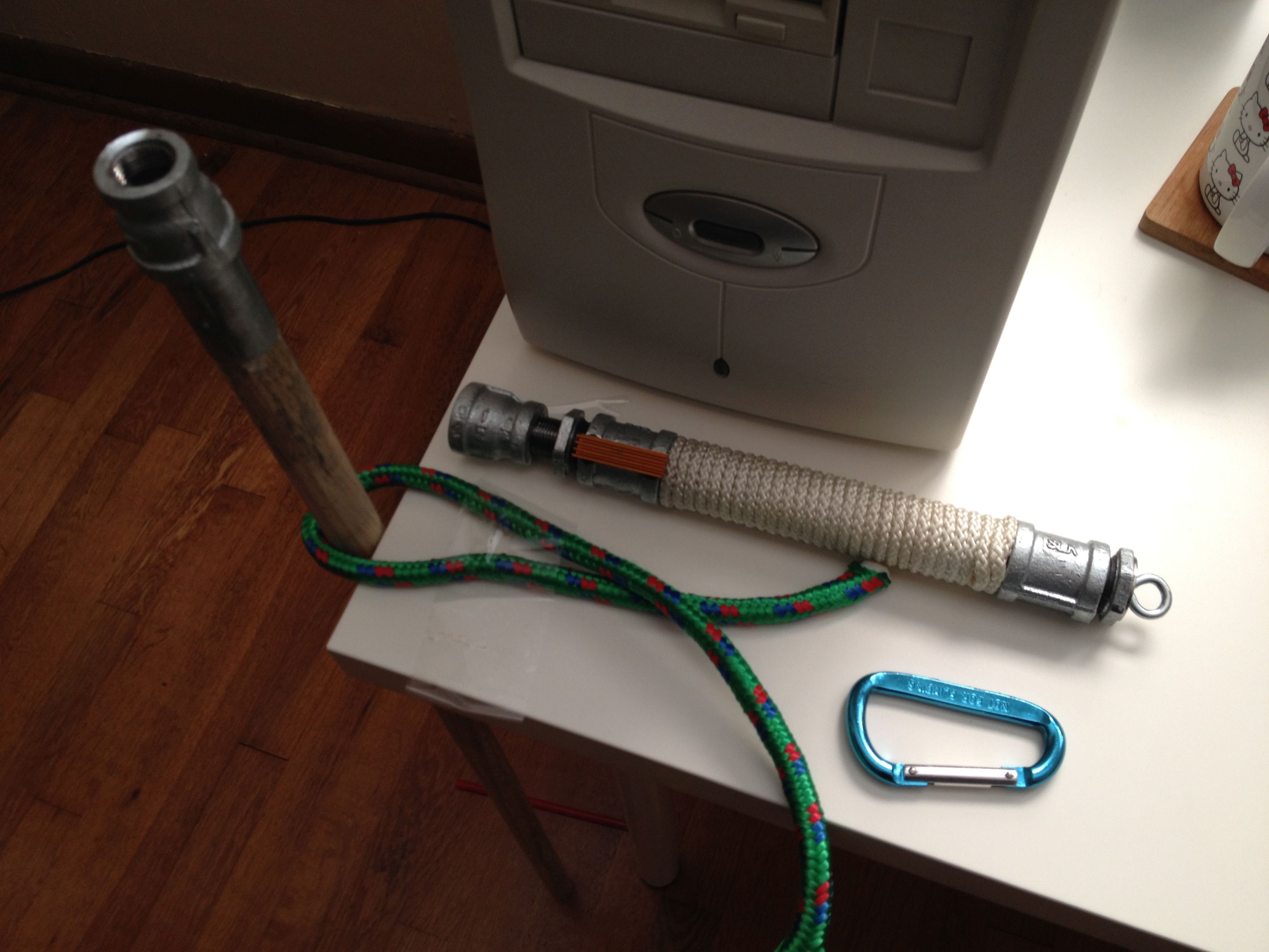
This was the first version of Luke’s lightsaber. I am working from memory as I do not have the lightsaber in front of me to give the exact specifications. I believe that working from the left to the right: 3/4″ to 1/2″ reducer, 1/2″ threaded pipe 1″ long, 1/2″ to 3/4″ bushing, 3/4″ coupler, 3/4″ pipe 7″ long, 3/4″ coupler, 3/4″ to 1/2″ bushing, flat washer with eye bolt affixed (epoxied into bushing). The orange lightsaber control attached to the first coupler is from a computer motherboard heatsink (sawed in half with a hacksaw) and epoxied to the coupler. The wrap is nylon rope.
In the next iteration, I replaced the nylon rope wrap with rubber o-rings that I ordered online (pack or 40 or 50). To install the o-rings, remove the last coupler on the right and roll down the o-rings one-by-one.
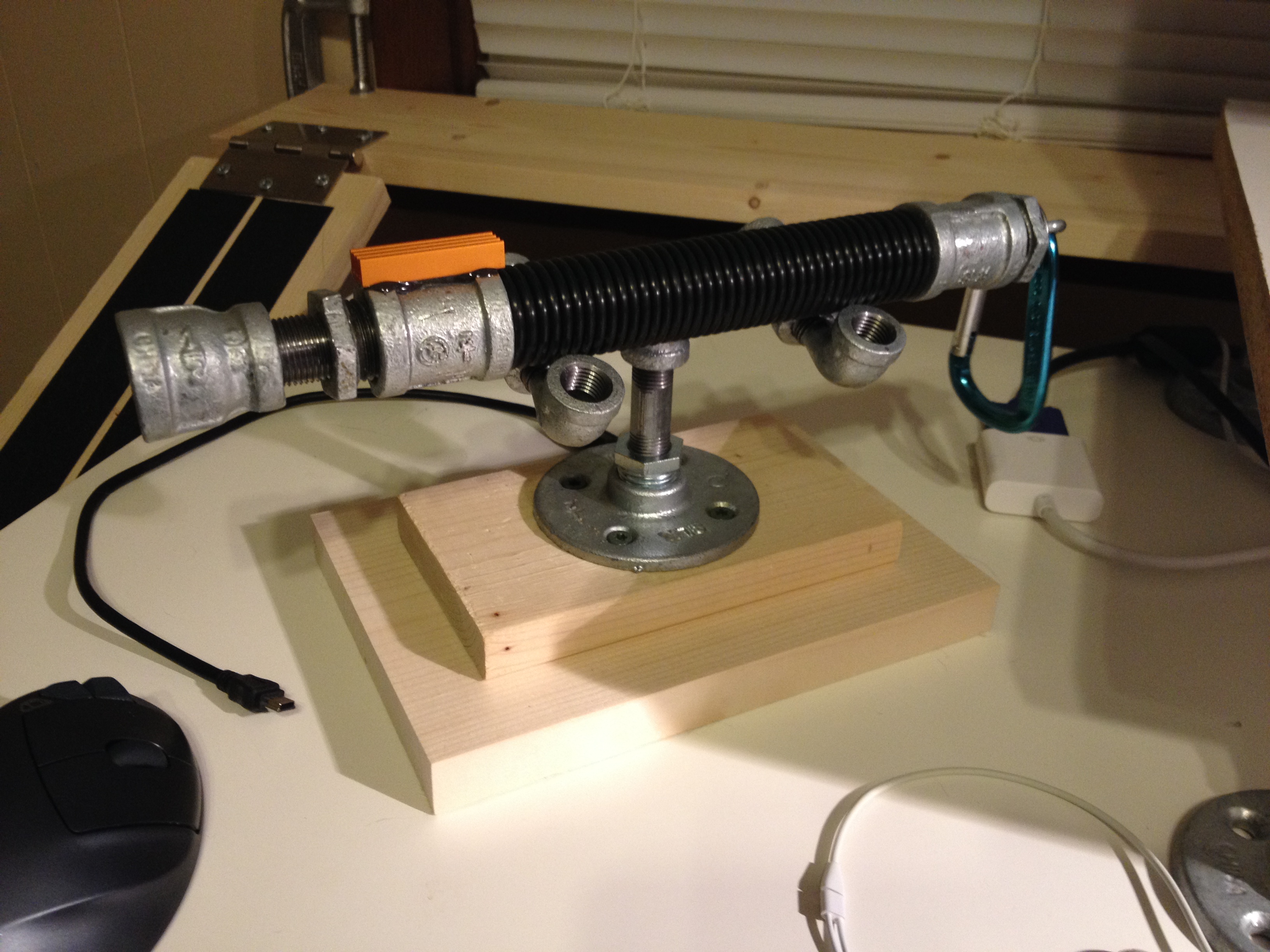
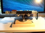
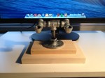
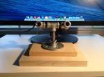
To display Luke’s lightsaber, I used smaller pipes attached to a wood base (two different sizes of lumber screwed together through the metal base connected to the pipes).
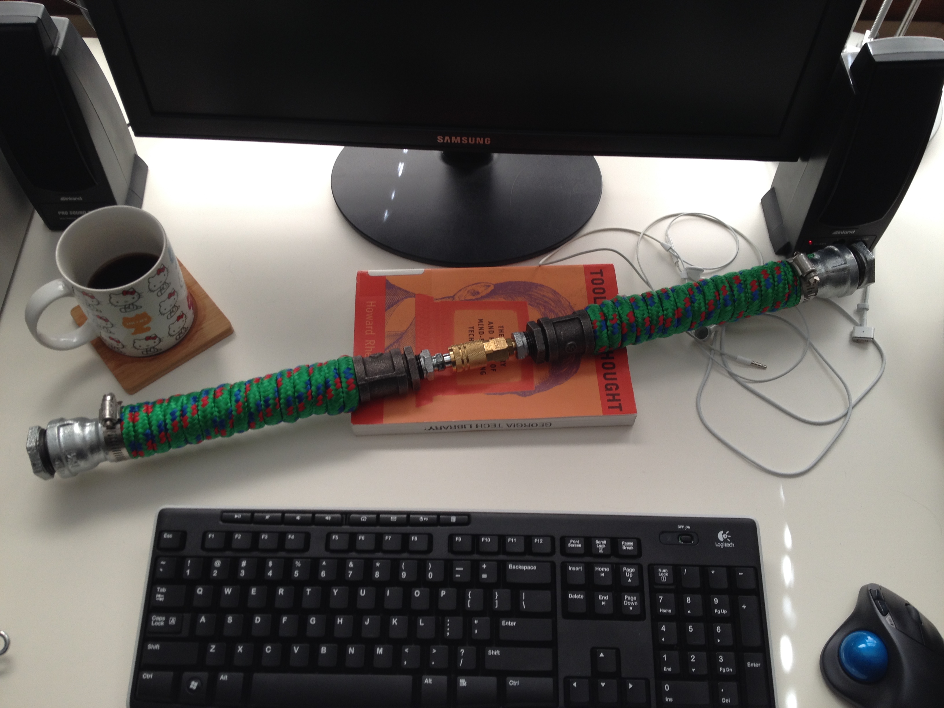
Darth Maul’s Double-Bladed Lightsaber
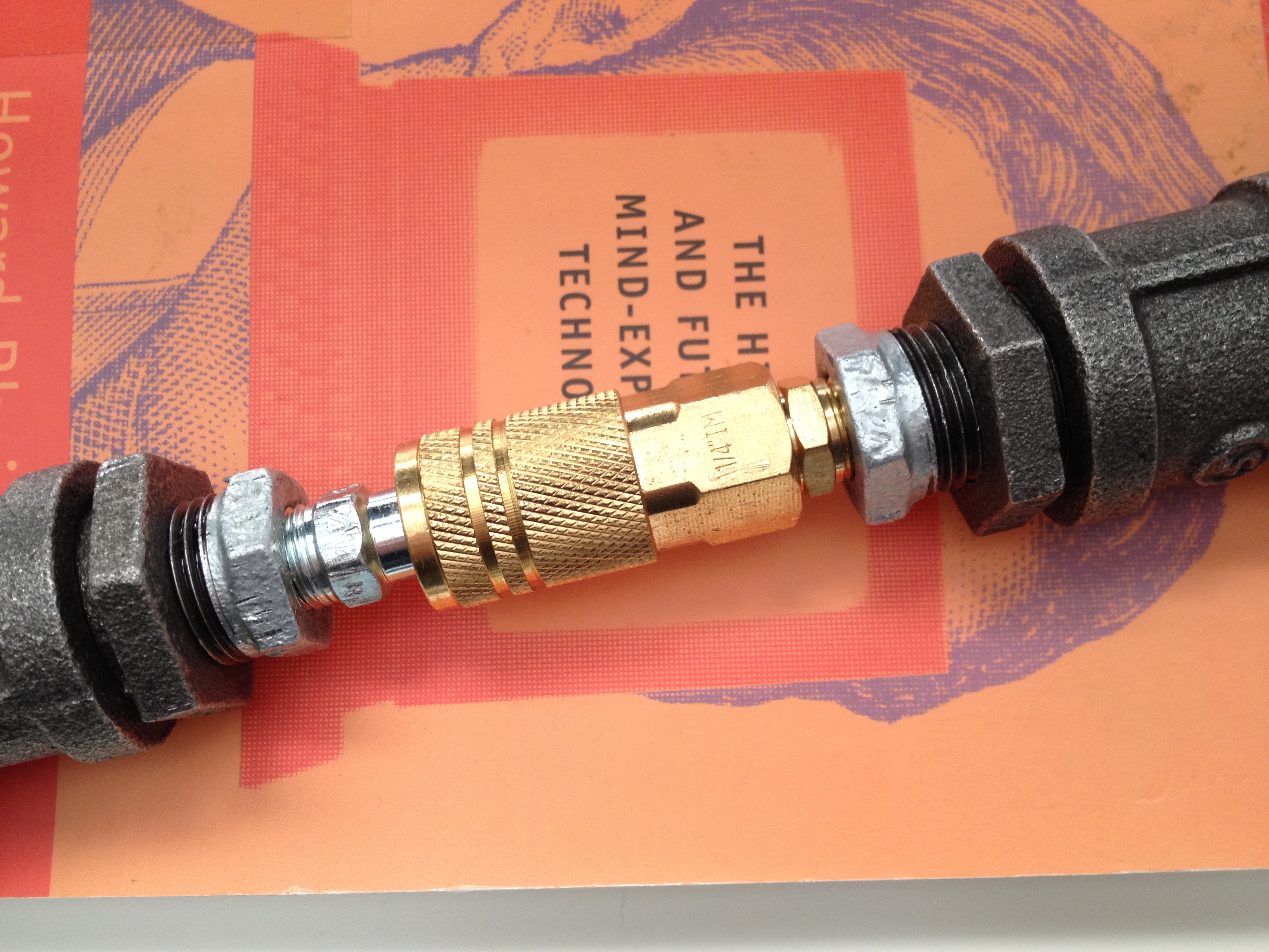
I built this Darth Maul inspired lightsaber as a way to figure out an easy way of having a two bladed saber that can split into two separate lightsabers. My solution was to use quick disconnect air hose fittings.
In order to make this work with the larger pipes used for Darth Maul’s lightsaber, which appears heftier in Episode I, I had to use two bushings to reduce down to the smaller size of the air hose fittings.
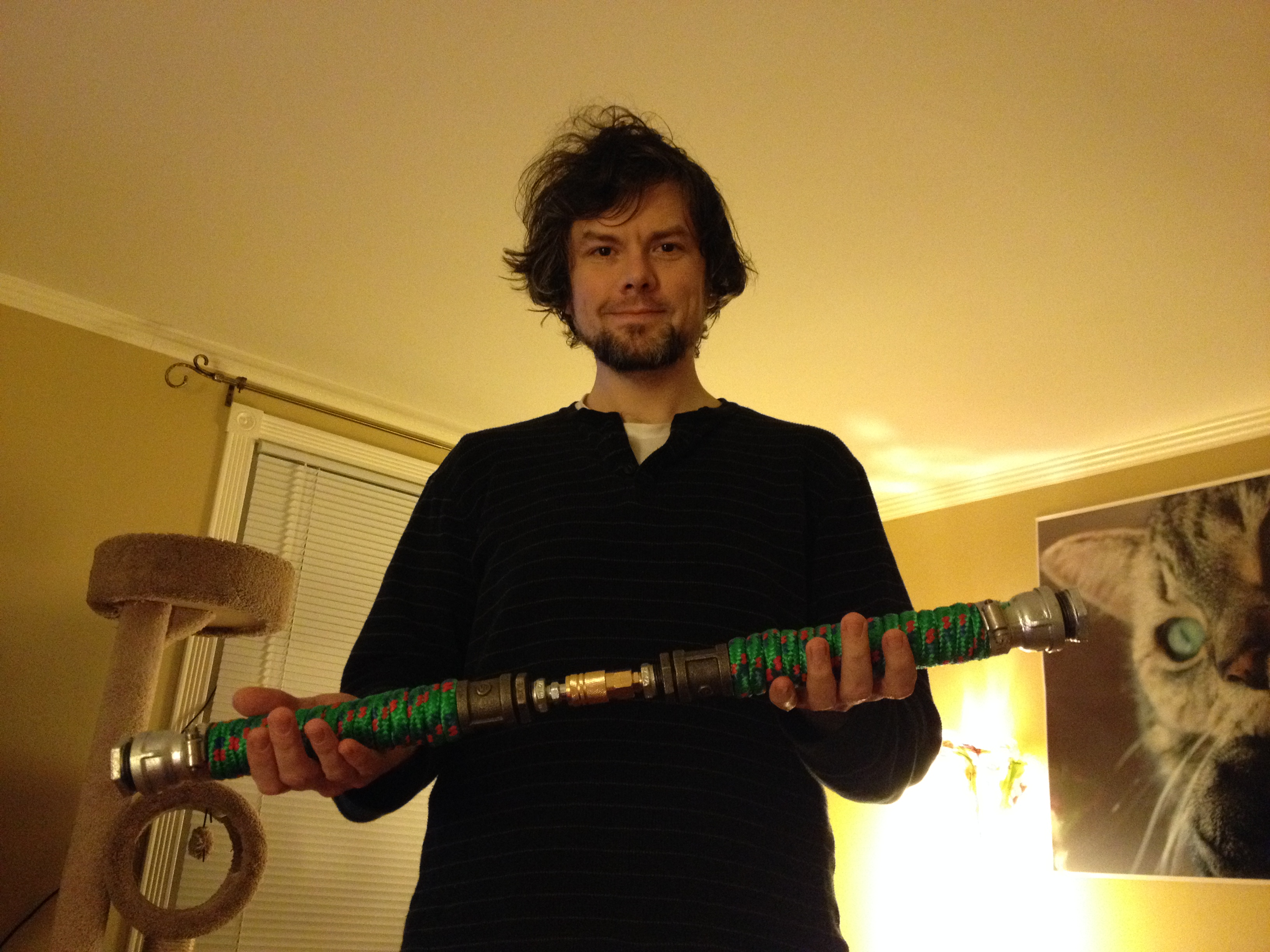
Here is the double-bladed lightsaber connected.
Here is the double-bladed lightsaber disconnected into two separate sabers. I didn’t build blade attachments for this saber, so I couldn’t test how much pressure/stress could be applied to the quick disconnect coupler that holds everything together. I suspect that this kind of assembly can only be used for show rather than demonstration of saber techniques (as I had constructed the two sabers above). With further modification, I believe that someone could sheath the quick disconnect coupler with metal so that the saber appears more solid from end-to-end instead of having this smaller, weak point in the middle as this demonstration saber appears.
I hope these extra photos and explanation help. Good luck with your builds, and please share any photos that you post online of your sabers in the comments below!