Tag: Lego

  • New LEGO Millennium Falcon 75105 Customization with The Last Jedi Update

    millennium-falcon-custom

    Over the years, I’ve built several customized LEGO Millennium Falcons (including here and here). I like taking the stock models and making them more screen accurate combined with imaginative embellishment. With this customization of a stock 75105 Millennium Falcon, I initially tried working this model that I had built about a year ago. However, I got really frustrated trying to work out how to implement some of the customizations that I had in mind. So, I disassembled the model and rebuilt it. Doing this helped me remember the logic of its design and construction, and it enabled me to rebuild some of its foundational features more easily than the piecemeal way I first attempted to do. The way that I did this rebuild also jumped around the instruction booklet, because the LEGO process of building is generally height-by-height across the whole model. I needed to focus on the modular aspects of the model, which is helped by building each module (circumferential ring, cockpit, docking ports, etc.). Due to rebuilding it from the ground up, this project took several days. Scroll through this blog post to view detailed photos and descriptions of this customization.

    Cockpit and Mandible Details

    Taking inspiration from Flail’s Millennium Falcon mods on Brickshelf, I rebuilt the cockpit with chairs and control sticks. This looks really nice, especially with the windows affixed. However, the chairs don’t work with Chewbacca’s minifigure. 75105 includes a Brick 1X4 W. 4 Knobs on either side of the fore mandibles. The side studs invite customization, so I added extra detail to these.

    IMG_3027 1.jpgIMG_3028 1.jpgIMG_2997 1.jpgIMG_3029 1.jpgIMG_3030 1.jpg

    Gun Turrets, Dorsal Vents, and Ventral Covering

    Inspired by Flail’s mods on Brickshelf again, I built these lower profile top and bottom guns. I beefed up the dorsal venting system by putting Plate Round 4X4 With Ø16Mm Hole with a Plate 2X2 Round in its center. The Disk Ø24 with vent sticker connects to the round plate in the center. The bottom of the falcon is buttoned up with plates covering the Technic support system–some of which I modified to remove the arm underneath the cockpit support system and added a staggered rounding to the four corners.

    IMG_2994 1.jpg

    IMG_3035 1.jpgIMG_3040 1.jpgIMG_3021 1.jpg

    IMG_2993 1.jpgIMG_2996 1.jpgIMG_2995 1.jpg

    Main Hold Entrance, Nav Computer, and Dejarik Table

    Using 1×1 roof tiles and an upside-down technique that I developed for a diorama of the Falcon’s main hold, I built this entrance into the main hold leading from the passage way from the entry ramp. The Dejarik Table and seating is borrowed from 75192. The Nav Computer area is very tight in the size of this model, so I couldn’t fit as large tubes adjacent to it as in the diorama linked above. Instead, I used two short tubes and moved the Nav Computer one stud to the left to accommodate the Falcon’s machinery. The main hold’s med bay is raised to accommodate a drawer, which I detail further at the end of this post to avoid The Last Jedi spoilers for anyone who hasn’t seen it yet.

    IMG_3022 1.jpg

    Millennium-Falcon-mainhold-entrance.jpgIMG_3018 1.jpgimg_3017-1.jpgIMG_3016 1.jpgIMG_3015 1.jpgIMG_3014 1.jpgMillennium-Falcon-mainhold-tfa.jpg

    Port and Starboard Docking Ports

    One disappointing aspect of the 75105 model is the docking ports. It sandwiches 1×2 plates between two Plate 6X6 Round With Tube Snap and covers that with two Plate 2X4X18°. The trouble with this design is that it doesn’t really show the cone-like taper of the docking ports. Earlier Millennium Falcon sets 4504 and 7965 did a better job with the docking ports. I decided to keep 75105’s sandwich to give the ports height, and then built up a capped tube circled by 1×2 plates each topped with a Roof Tile 1 X 2 X 2/3, Abs.

    IMG_3042 1.jpgIMG_2991 1.jpgIMG_2989 1.jpg

    Wall Tile Extensions Around Circumference

    The Millennium Falcon dorsal and ventral domed covering extends over the circumferential edge. The 75105 model comes with 1×6 flat plates to demarcate this edge overhang, but it doesn’t really look right. I picked up a lot of Wall Element 1X2X1 on Bricklink to replace these 1×6 flat plates. In addition to showing this circumferential trench around the edge of the Falcon, it gives the model an overall flatter look, which emphasizes the Falcon’s on-screen appearance.

    IMG_3033 1.jpgIMG_2992 1.jpgIMG_3040 1.jpg

    Engine Compartment

    Instead of the Falcon having a monolithic motor, it seems more likely that it would have a segmented, modular aerospike engine. With this in mind, I designed the engine compartment to have a ring of engine modules with supporting hardware, cabling, and pipes. I created a larger, ringed passage way with an entrance way leading into the engine compartment.

    IMG_3025 1.jpgIMG_3023 1.jpgIMG_3013 1.jpgIMG_3012 1.jpgIMG_3011 1.jpgMillennium-Falcon-aft-engineroom-entrance.jpgMillennium-Falcon-aft-engineroom-sideview.jpgMillennium-Falcon-aft-passageway.jpgIMG_2999 1.jpg

    Entrance Ramp and Other Compartments

    I stole the hydraulics from 75103: First Order Transporter and added to the Falcon’s entrance ramp (which makes the ramp look like the Kenner Millennium Falcon vehicle from the original Star Wars action figure line). Also, I shifted the entrance ramp one stud out from the central gunner turret assembly. There are two side compartments–one for storage with weapons in a crate, and one for another bunk (with a copy of the Death Star plans).

    Millennium-Falcon-entryramp-interior-down2.jpgMillennium-Falcon-entryway-interior-down.jpgMillennium-Falcon-entryramp-exterior-down.jpgMillennium-Falcon-aft-storeroom.jpgMillennium-Falcon-aft-sleep-compartment.jpg

    New Engine Exhaust and a Little Joke

    Instead of using the ribbed, transparent blue tube that comes with 75105, I opted for white tile backgrounds covered by transparent blue flat tiles (1×2 and 1×4). As a hidden joke, I included a trailer hitch under the engines (isn’t the Millennium Falcon is a big rig in the stars?).

    IMG_3038 1.jpgIMG_3039 1.jpg

    The Last Jedi Update

    At the end of The Last Jedi, Finn puts Rose in the Millennium Falcon’s med bay in the main hold. The camera focuses on the drawer under the bed when Finn looks for a blanket. The audience realizes that the drawer also contains the Jedi books on Ahch-To. To represent this, I raised the med bay, added a drawer beneath, and included a book (from The Hobbit set #79003: An Unexpected Gathering).

    IMG_3024 1.jpgIMG_3020 1.jpgIMG_3019 1.jpg

  • Desktop Shelving Epic Continues: Notched Shelf Added in the Middle

    shelf-progression

    What began as a simple shelf to raise some of my LEGO sets off the workspace of my desk and rose to incorporate a higher shelf to accommodate more sets that I brought back from my parents’ home is now a three tier Franken-shelf.

    It quickly became evident that I needed more shelf space for a few more sets that I had assembled. Also, I noticed that the 16″ space between the lower and upper shelves of the second phase construction was more than necessary. It seemed that 8″ headspace was required for most of my LEGO sets. So, I set about adding a third shelf between the lower and top shelves.

    I decided to notch this 1″ x 10″ x 4′ shelf and install it only with deck screws through the upper shelf supports. I measured 46 1/2″ between the two supports and the 1″ x 4″ supports are 3/4″ thick. This is where I made a mistake with my initial cut. My measurements were correct, but during the 5 seconds that it takes for me to talk from my closet (where the desk is) to the living room where I had left my handsaw, my mind misremembered the measurement as 46″ between the supports. This meant that I cut 1/4″ more than needed on each side of the shelf! Luckily, I had a scrap piece of 1″ x 4″ board that I cut 1/4″ fillers from and glued into the notch to fill the missing material.

    IMG_2117

    The shelf is centered on a line at 8″ between the top of the bottom shelf and the bottom of the top shelf, which is a distance of 16″.

    IMG_2118

    My deck screws extend through the supports and filler, and enter the shelf securely. They are spaced 1″ inside from either end and the third being in the middle (3/4″ from either end screw).

    IMG_2116

    The new shelf easily accommodates a number of sets from Star Wars, Lord of the Rings, Harry Potter, and Doctor Who.

    IMG_2115

    If I had planned out the shelves better than I had, I would have built the entire thing using only wood and deck screws (my previous blog posts explain how I used metal brackets and braces). This would have lowered the cost and it would have had a better craft appearance than horribly kludge-like. Nevertheless, it gets the job done–I can see my sets above and continue building on my clearer workspace below.

    IMG_2114

  • More LEGO, Another Shelf

    before-after-shelves

    In my previous blog post, I documented a shelf that I built for my low-cost Ikea desk.

    Since then, I brought back two checked bags full of LEGO from my parents’ home in Georgia where I had been storing it. I have not put all of these sets together or sorted the loose bricks into bins, but became quite clear after assembling 2/3 of the sets and two additional sets from eBay that I would need at least one more shelf.

    To add another shelf, I needed to shore up the existing shelf and build up from it.

    Two constraints to the height between the two shelves were the enormity of the Tower of Orthanc (10237) and the height of the room’s ceiling. I settled on a height of 16″ between the two shelves to allow enough room for medium- and small-sized sets on the lower shelf and larger sets (including Saruman’s lair) on the upper shelf.

    To add the new shelf, I needed to purchase one 1″x10″x4′ pine board (the shelf), two 1″x4″x4′ pine boards (one of these was cut in half to support the lower, existing shelf and the other was cut into two 16″ long lengths to support the upper, new shelf), two packs of 1 1/2″ braces, and two packs of 2″ brackets (the smaller brackets that I used for the original shelf were sold out at the local Lowes).

    IMG_2067.jpg

    To shore up the lower shelf, I added a 24″ support to the front of the shelf. Originally, there was only one 24″ support at the back of the shelf, which was plenty for the needs of accommodating the few LEGO models originally put there. With the additional weight higher up from the new, upper shelf, I wanted to ensure that the lower shelf on which the upper shelf is built can sustain the weight and any torsion. I affixed each of these new, forward supports with two deck screws (pre-drilled) from the top of the shelf into the stop of the support. At the bottom, they are held in place with braces on the outside against the edge of the desk top.

    IMG_2072

    IMG_2068.jpg

    The upper shelf has two 16″ supports that affix to the back of the lower shelf. The upper shelf is attached to the supports first with two deck screws (pre-drilled) from the top through the shelf and into the supports. On the outside, they are connected to the lower shelf by a brace on either side. The shelf is strengthened with a brace at the top, too.

    On the inside, brackets are used where the support meets the lower shelf’s top and the upper shelf’s bottom. Instead of using the metal braces, I could have used wood braces–such as another 1″x4″x4′ board running underneath the shelf and cut 3/4″ on either end to accommodate the supports. A few deck screws from top and sides would have made the shelves even stronger. I wanted to avoid the shelves catching more light in my dark office than they could, so I opted to use the metal brackets, which should be strong enough for this installation.

    IMG_2066

    Now that the new shelf is installed, I realize that I need another shelf! Maybe I can fit one in between the lower and upper shelf. As you can see above, I can’t go any higher on the upper shelf or Saruman will go through the roof!

  • How to Add a Shelf to an Ikea Table Top Desk for About $16, with Thoughts on Making

    IMG_1835

    I believe that it is important for everyone to make things. Making uses the brain and the body. Making acts on the world. Making is an expression of ourselves. Making can be for ourselves alone or it can be shared with others. Making can be meta, too–making about making (like this blog post). Making in all of its forms is a really big part of what makes us human.

    Doing a bit of making today, I built a raised shelf for my IKEA table top desk using pine boards. It began as a thing for myself, and it continues as a thing shared with you here.

    I like working with wood. Unfortunately, I don’t get to build things with wood as often as I would like. When I lived in Atlanta, I had space and tools. Here in New York, I have little of the former and few of the latter. Nevertheless, I find small ways to stay in the woodworking game by building things to solve problems such as the state of my work-at-home desk:

    IMG_1810

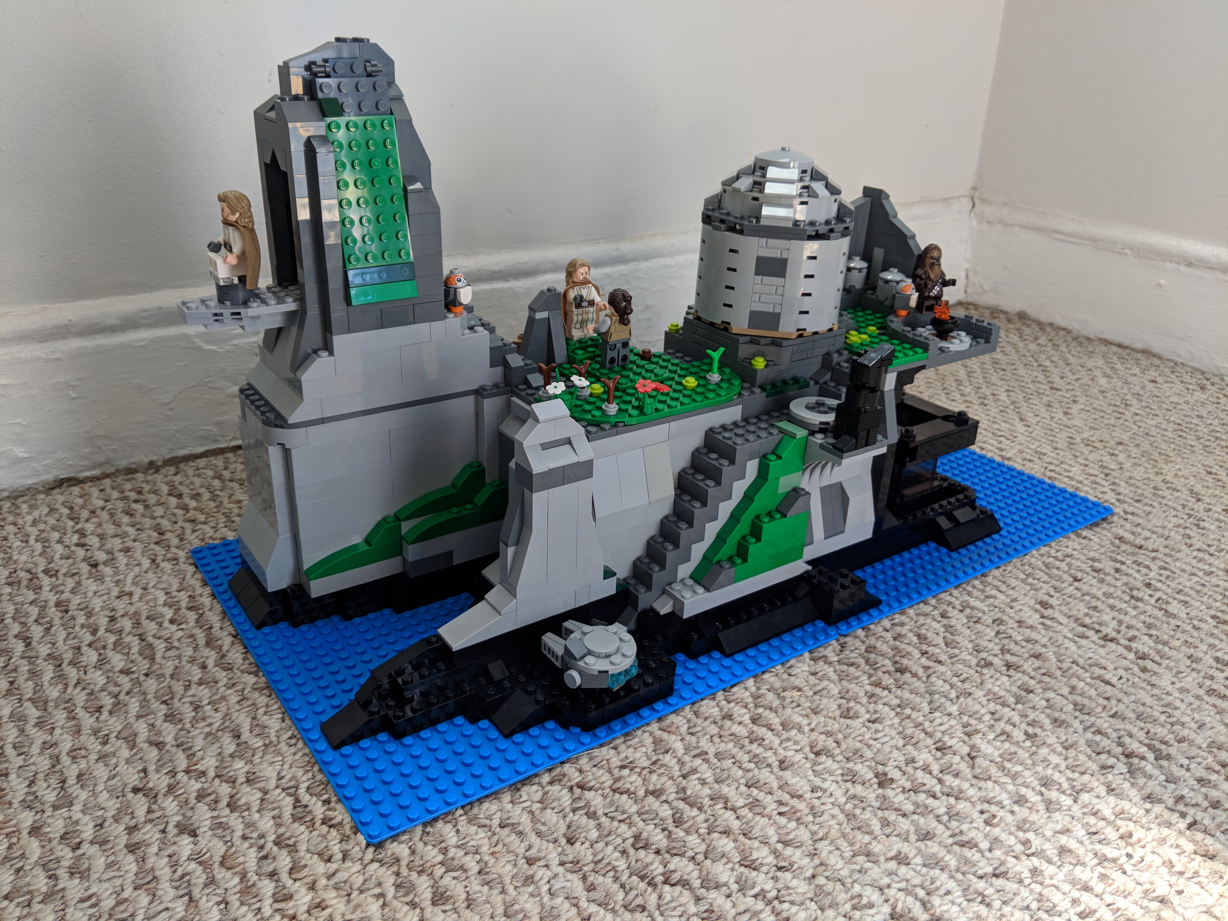
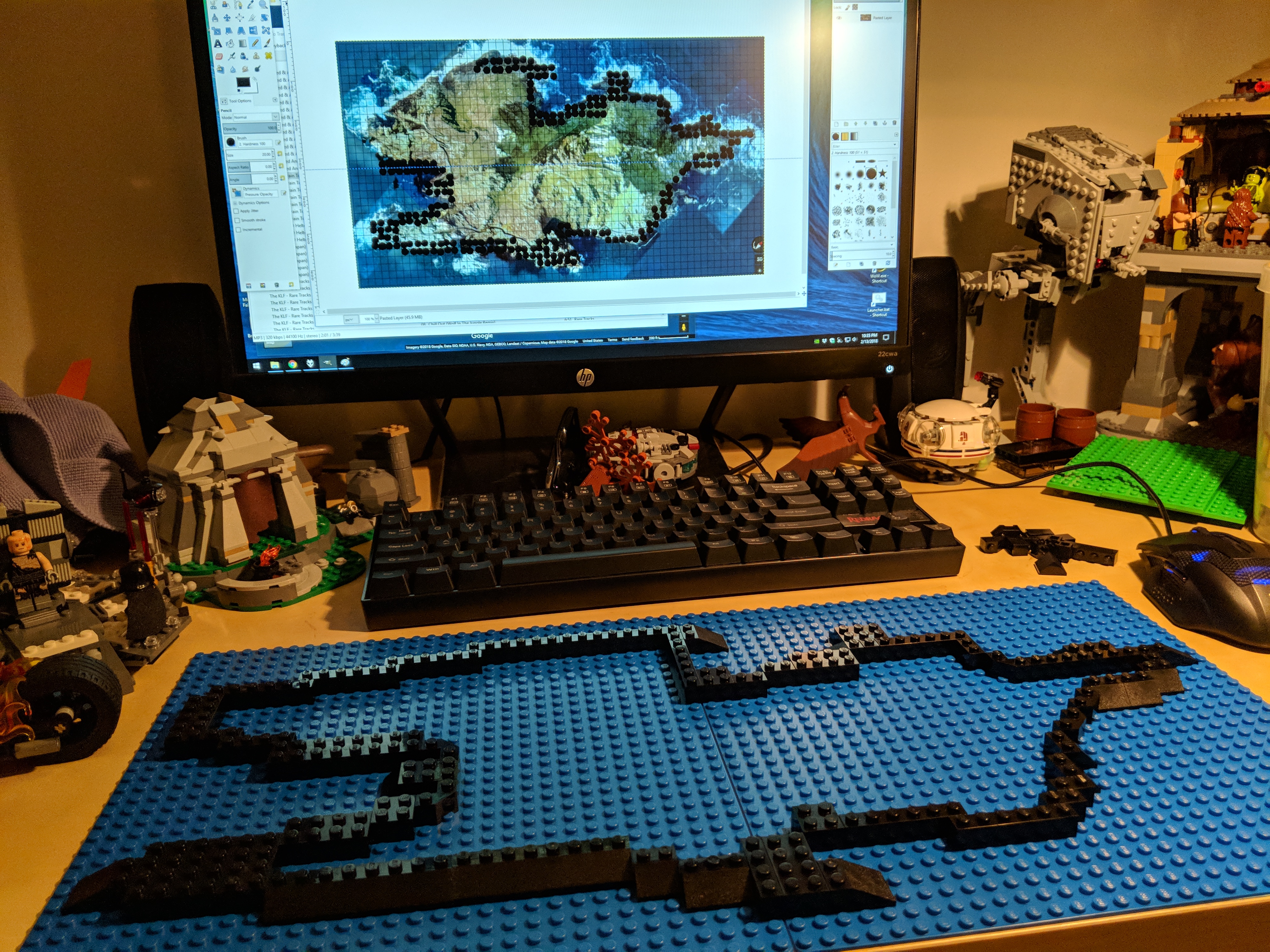
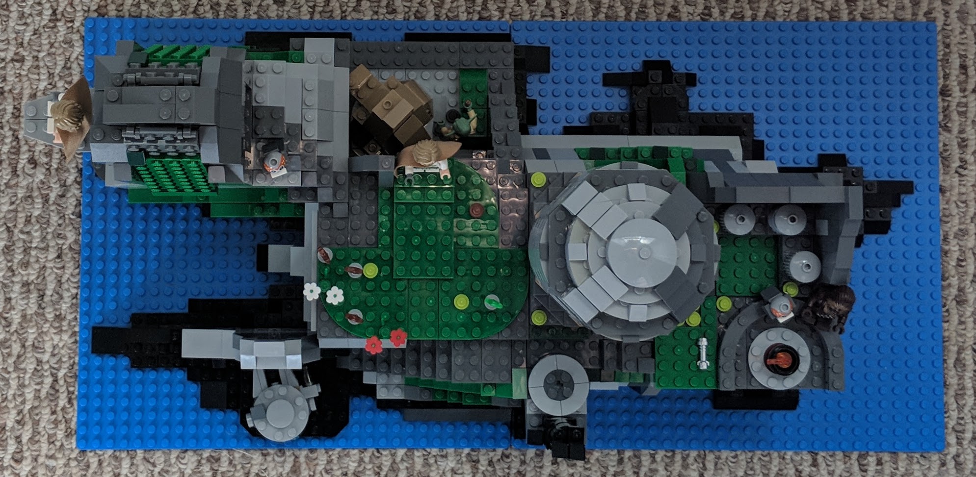
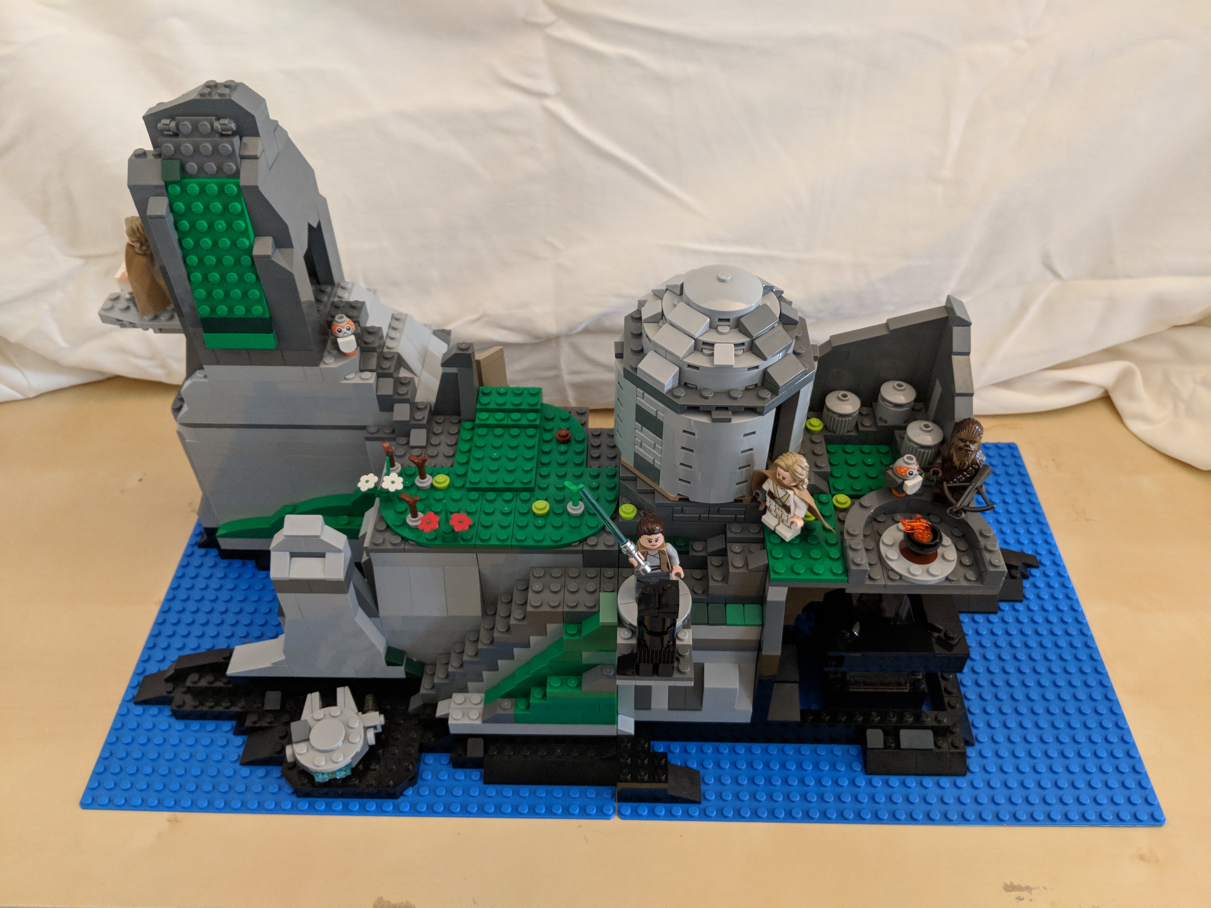
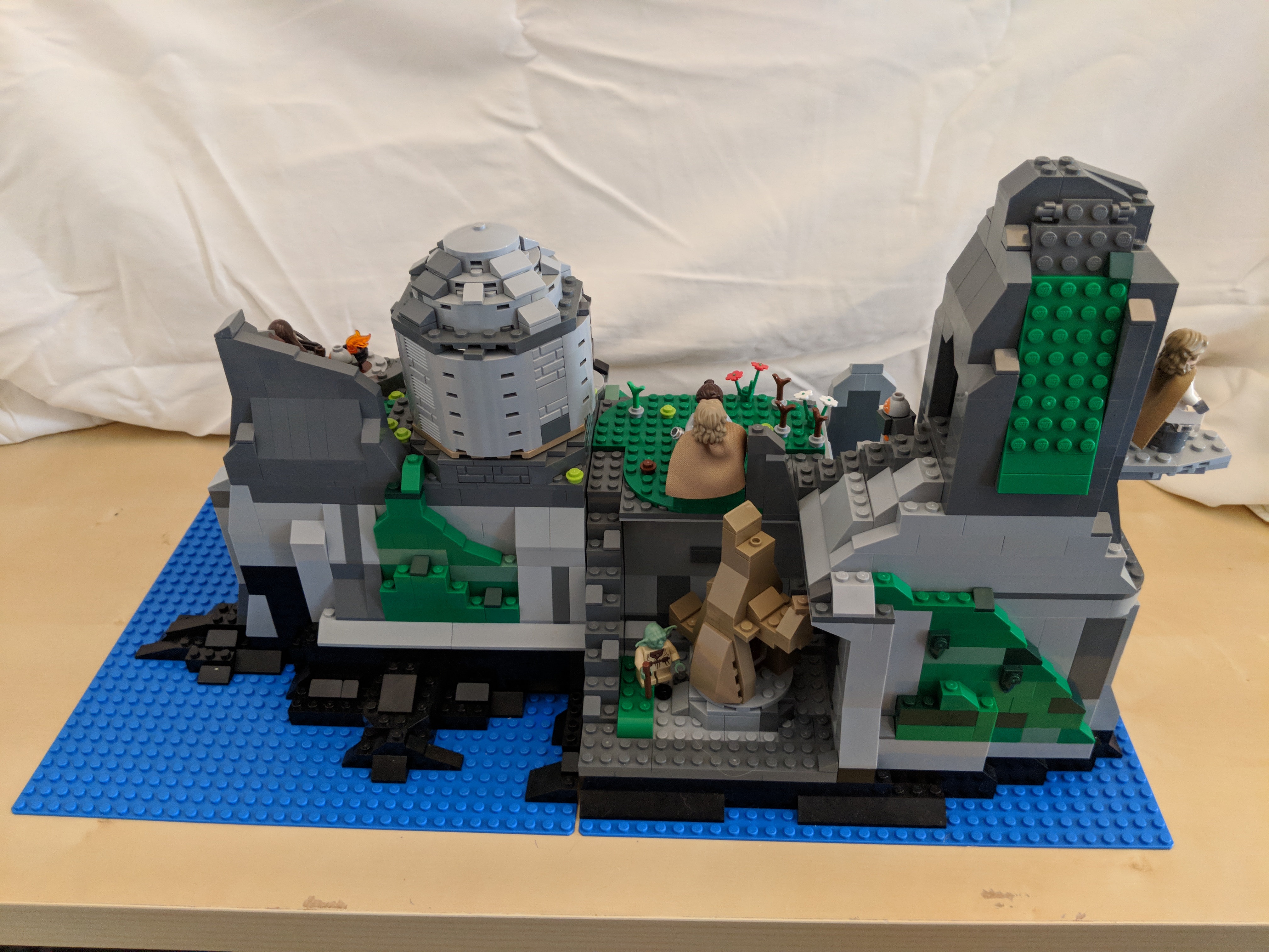
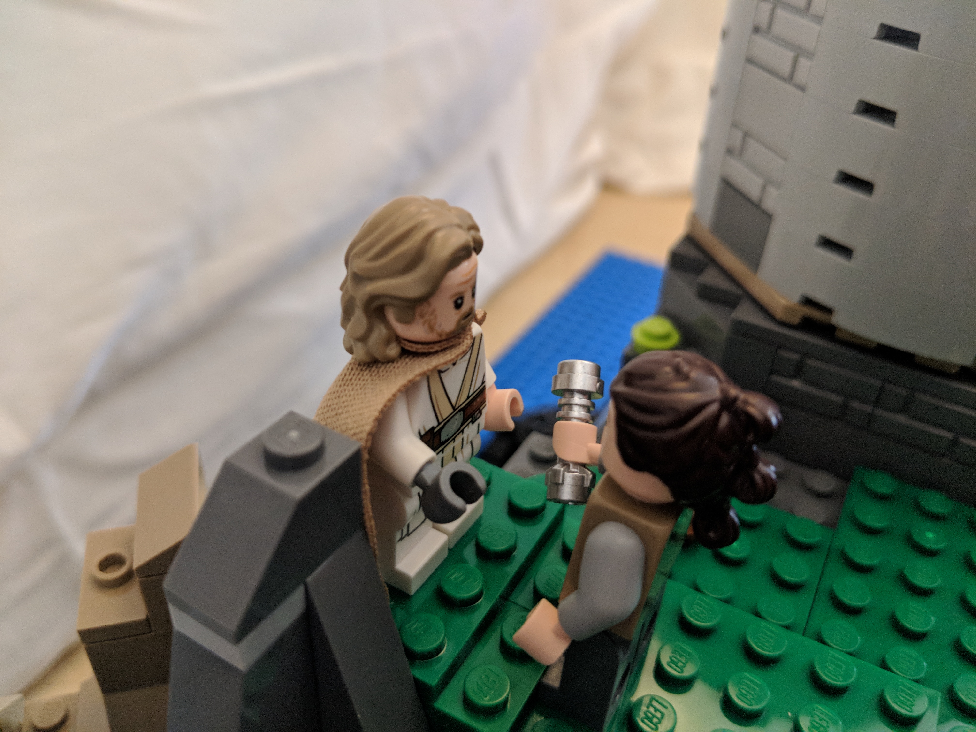
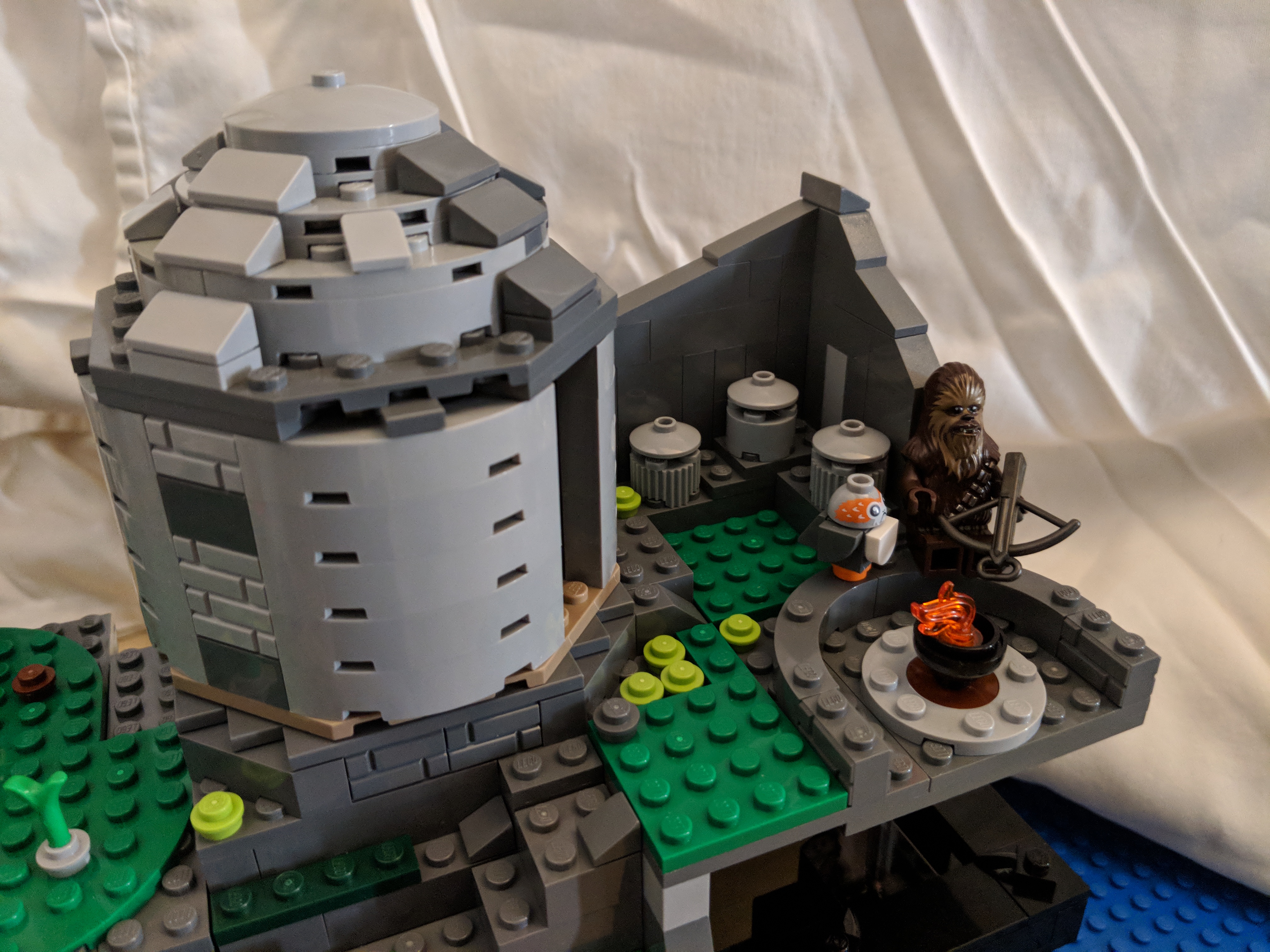
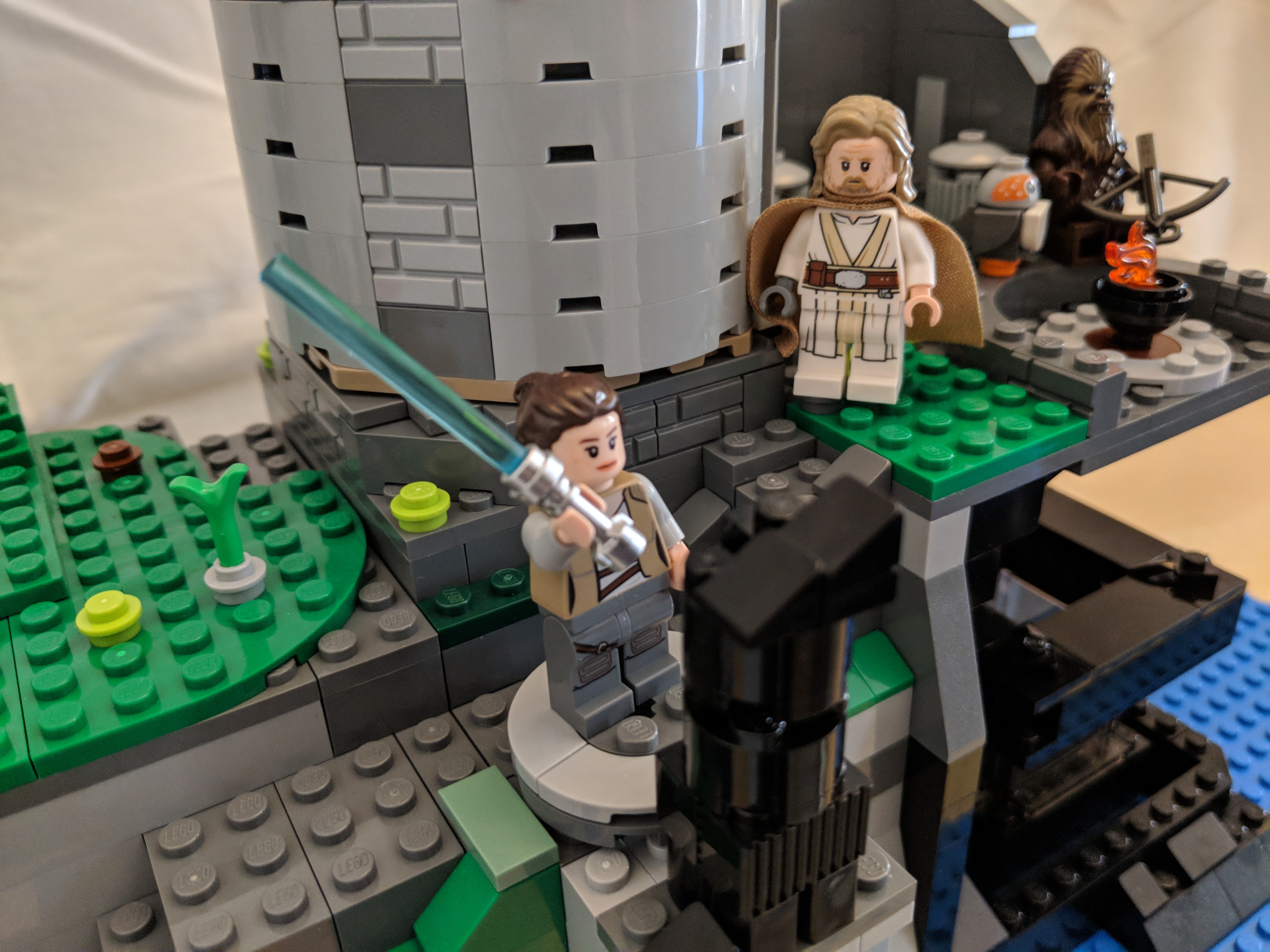
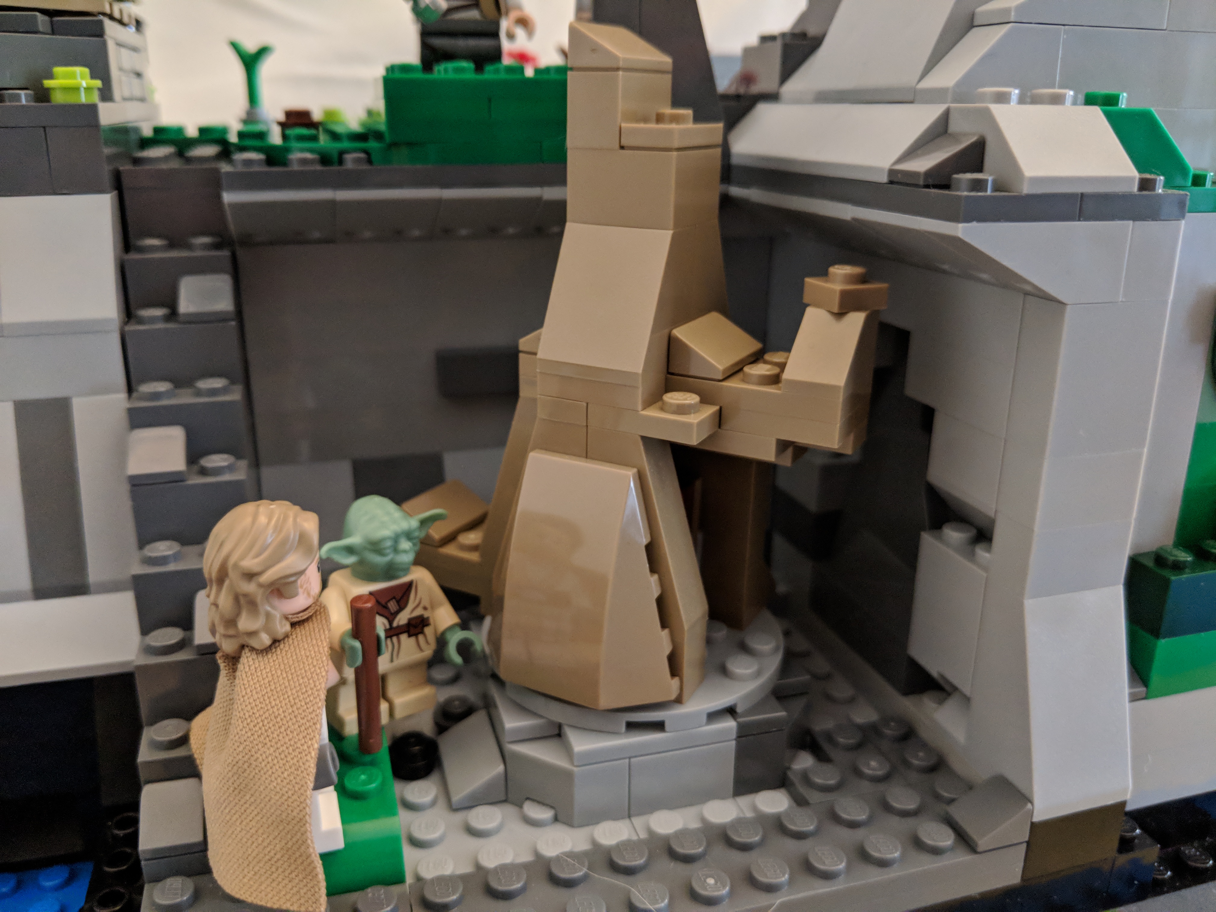
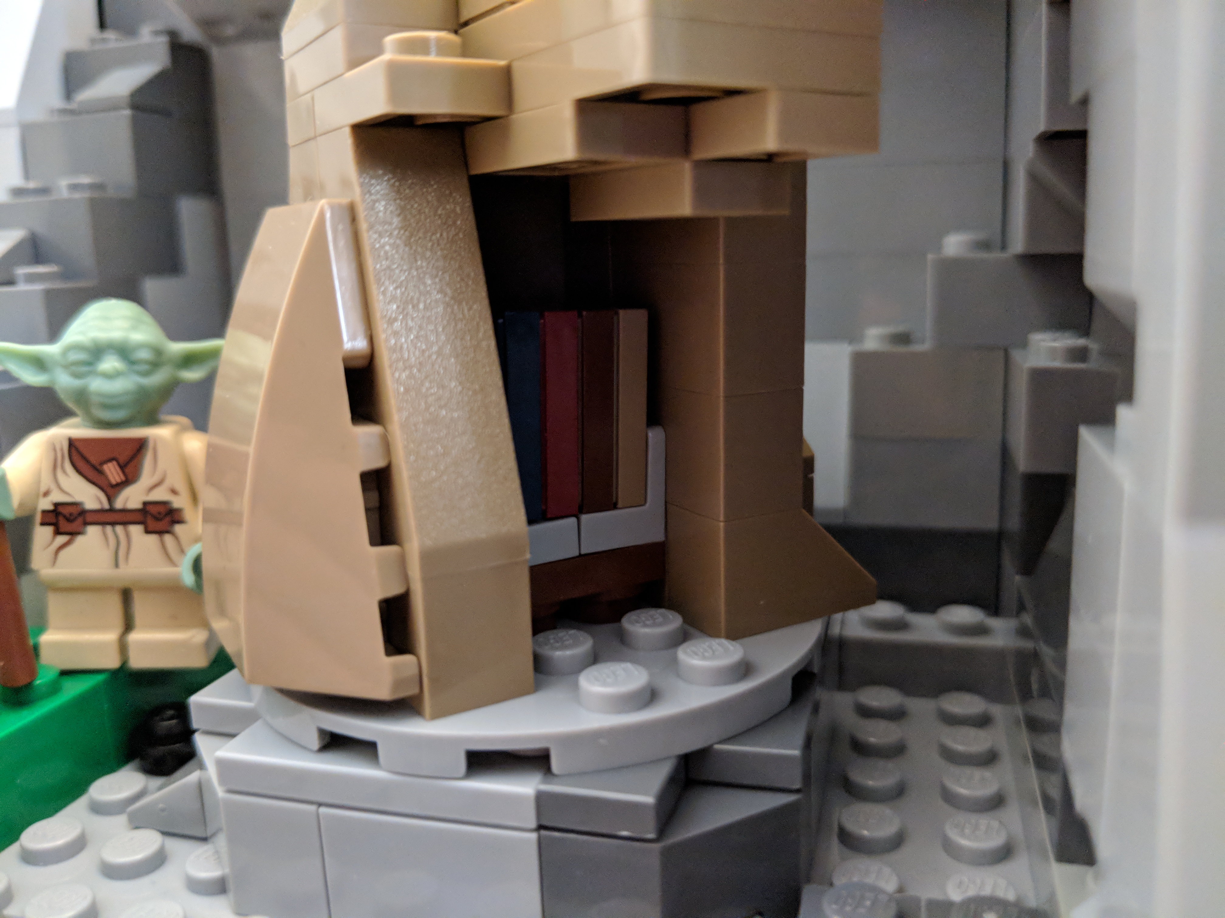
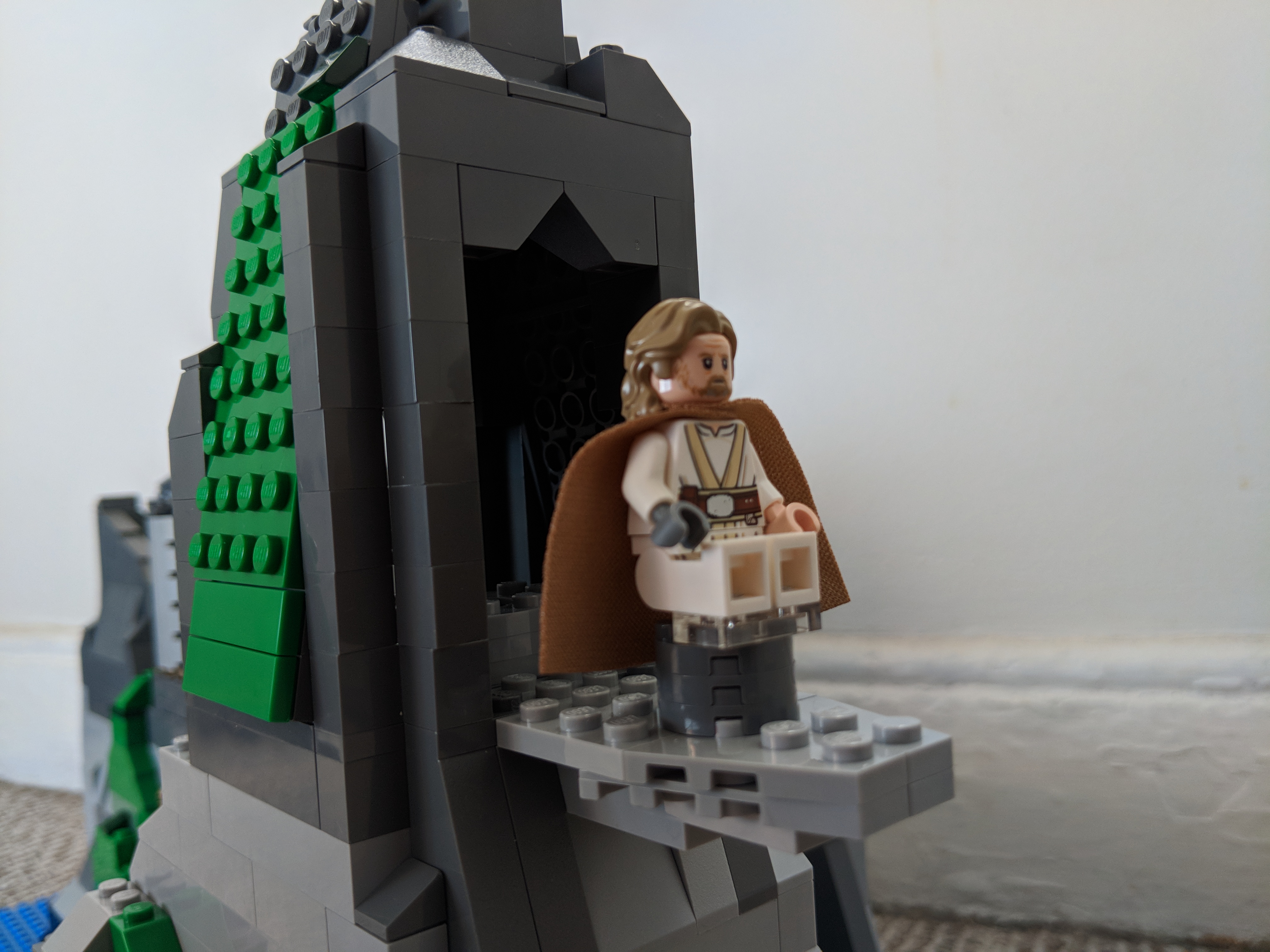
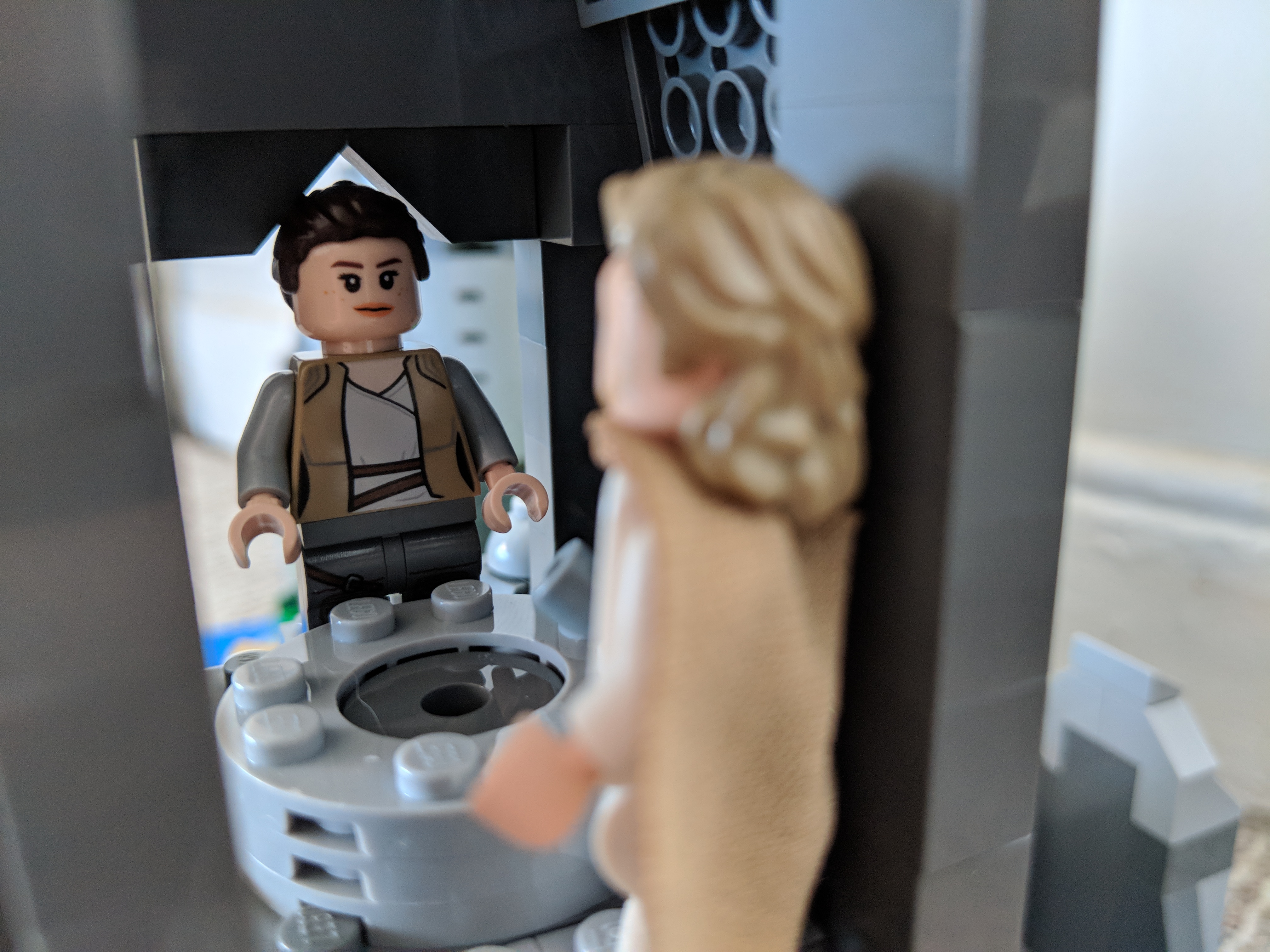
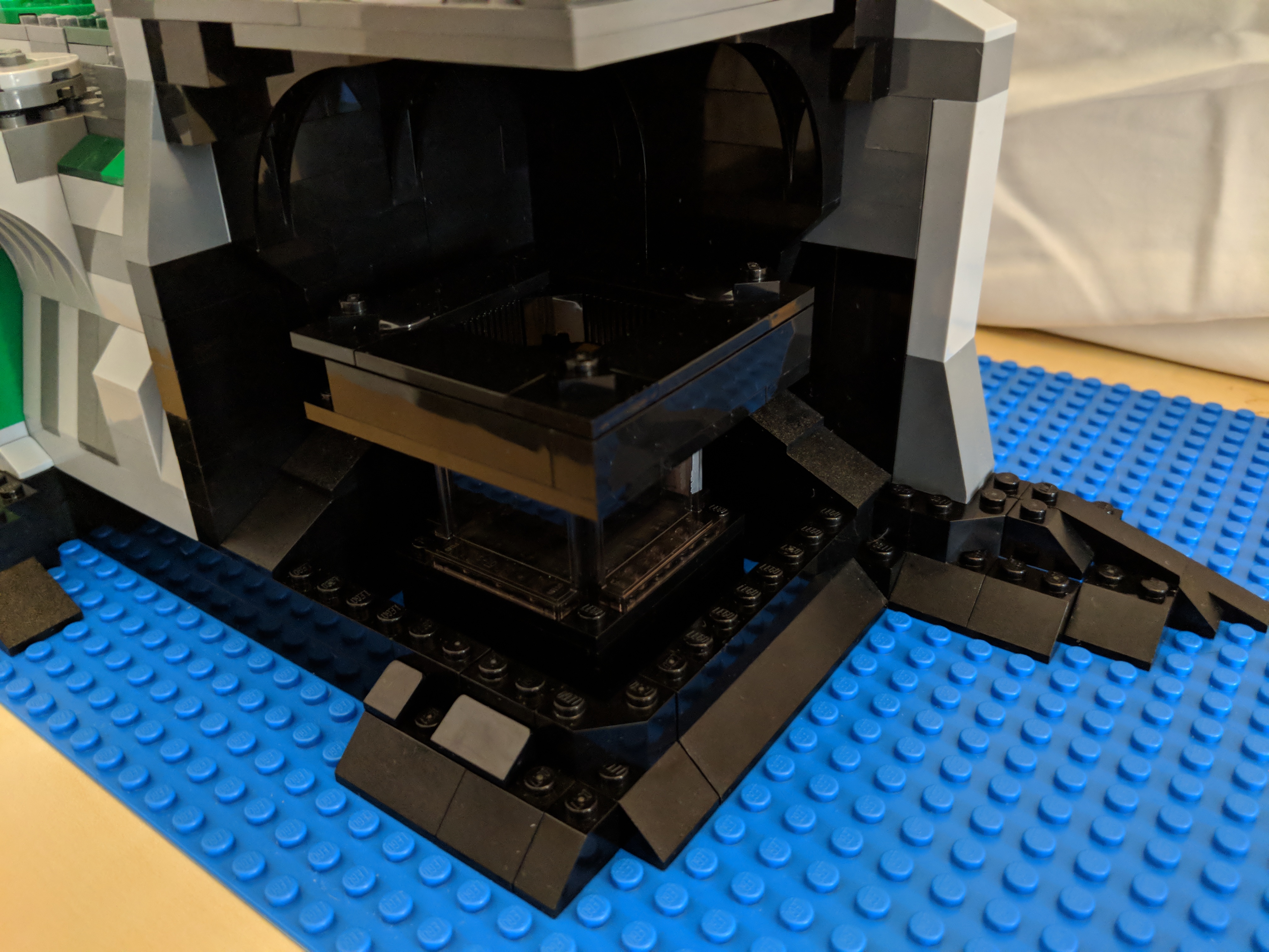
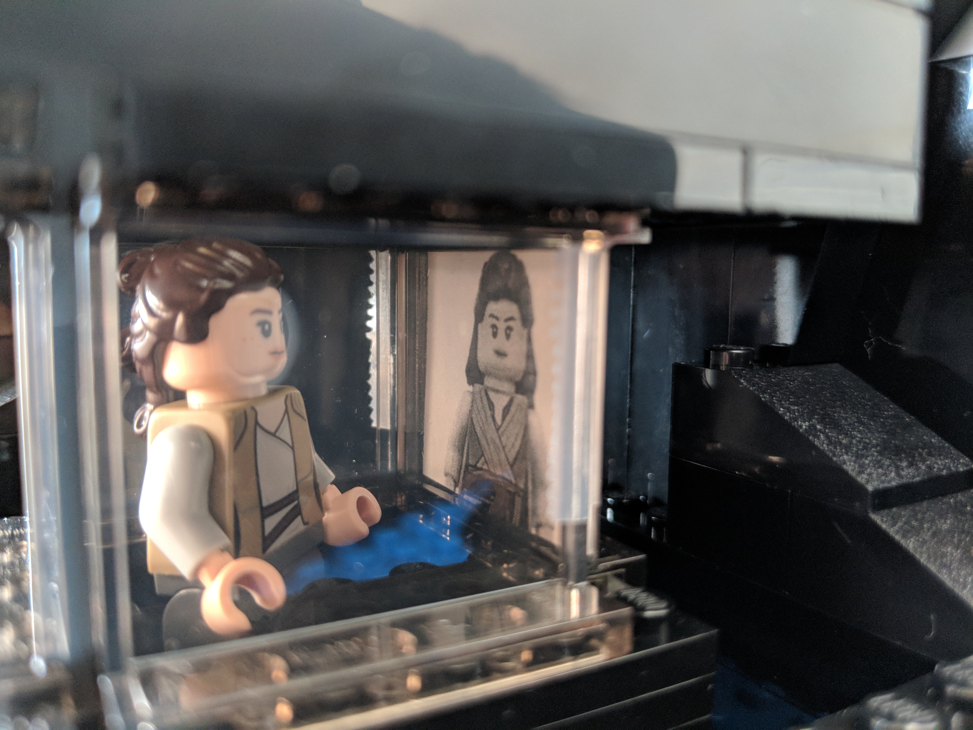
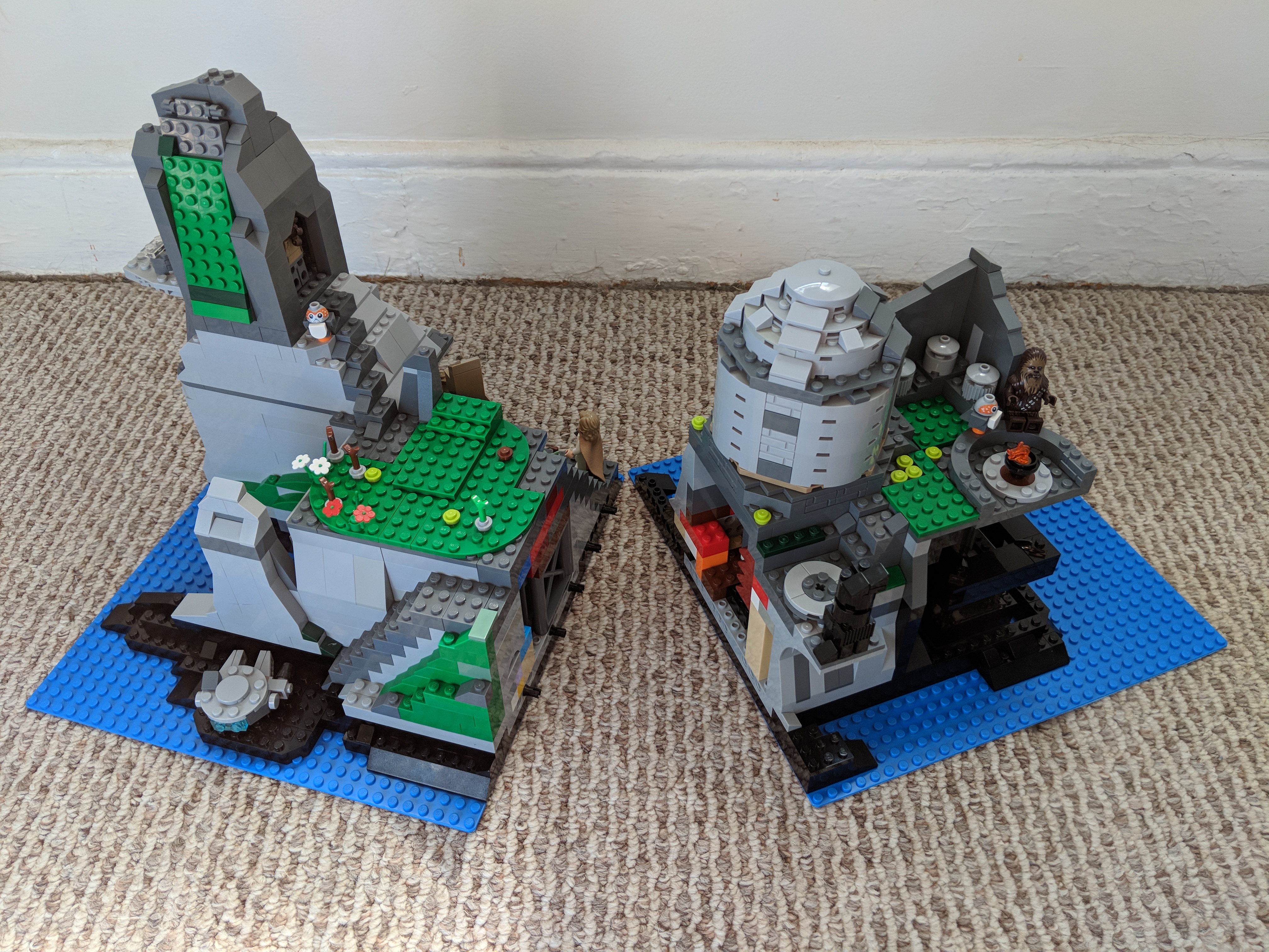
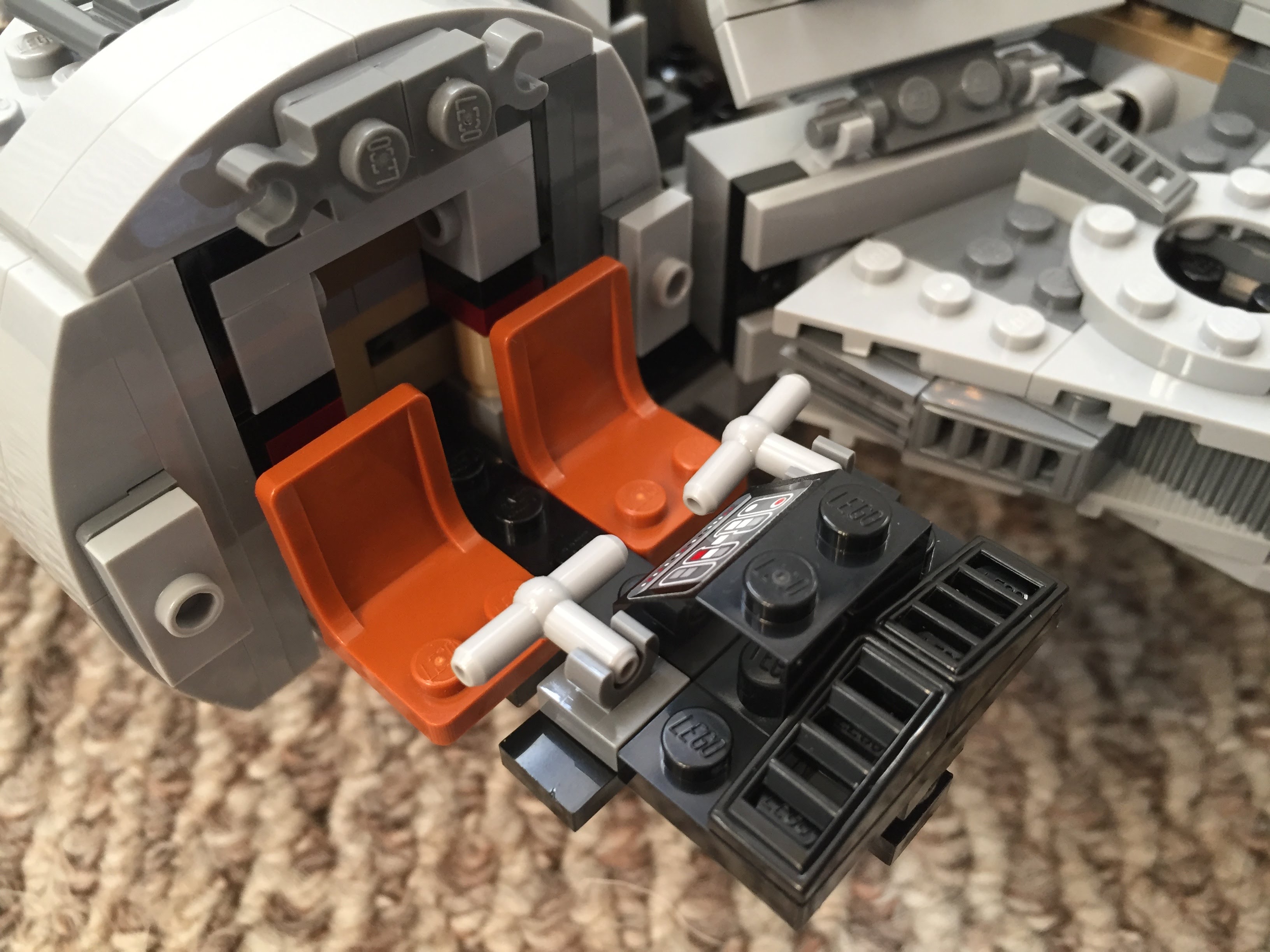
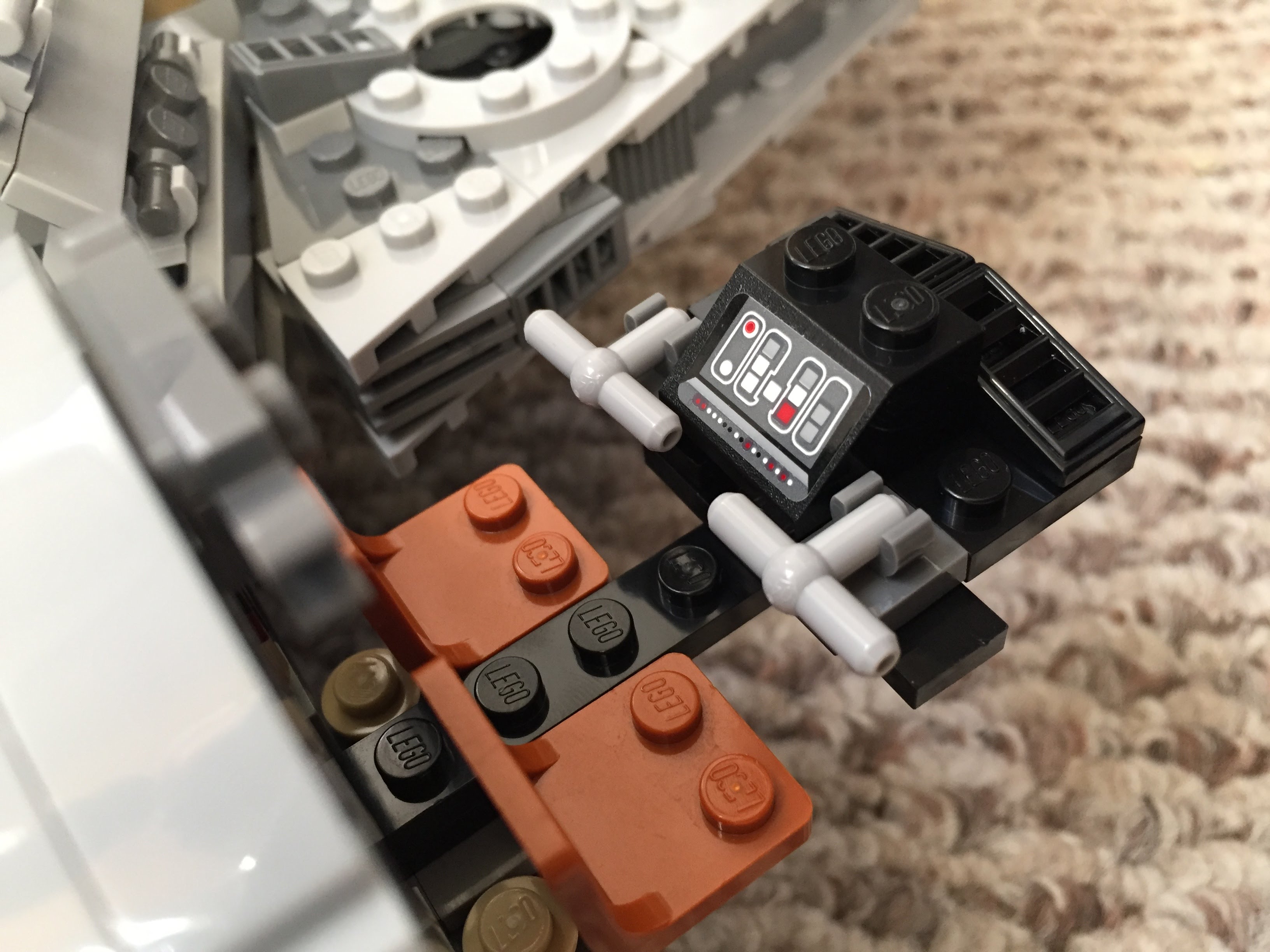
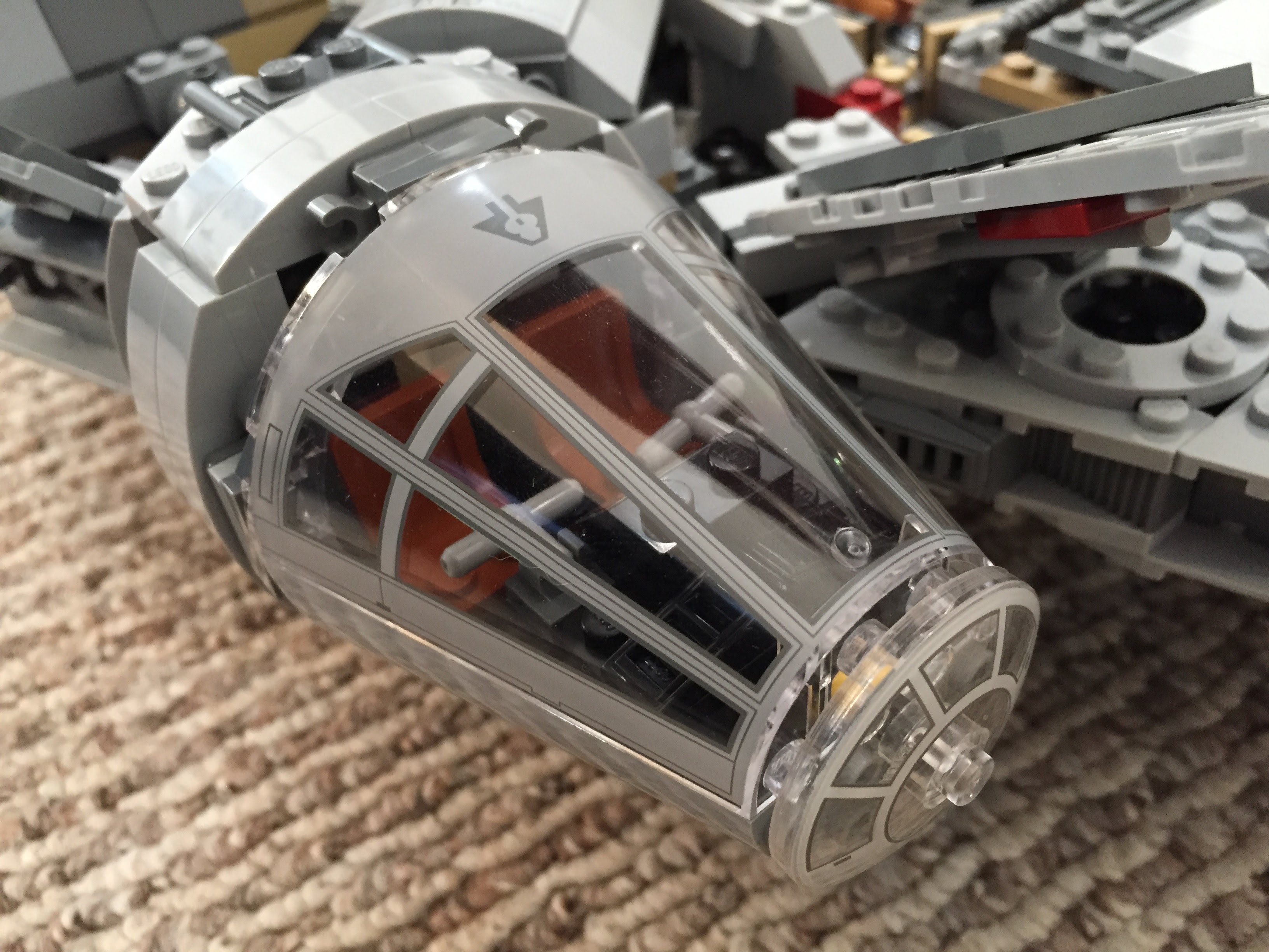
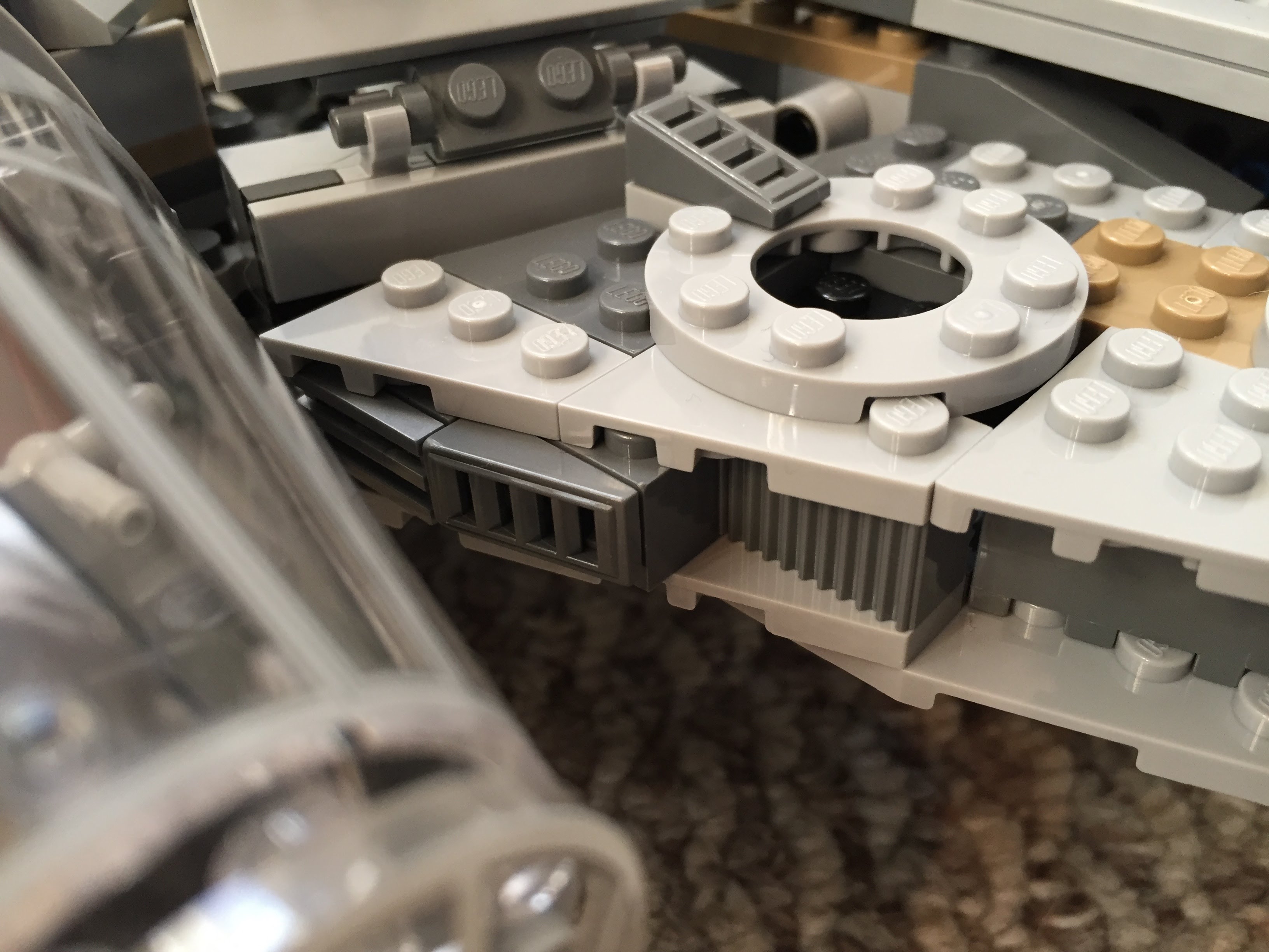
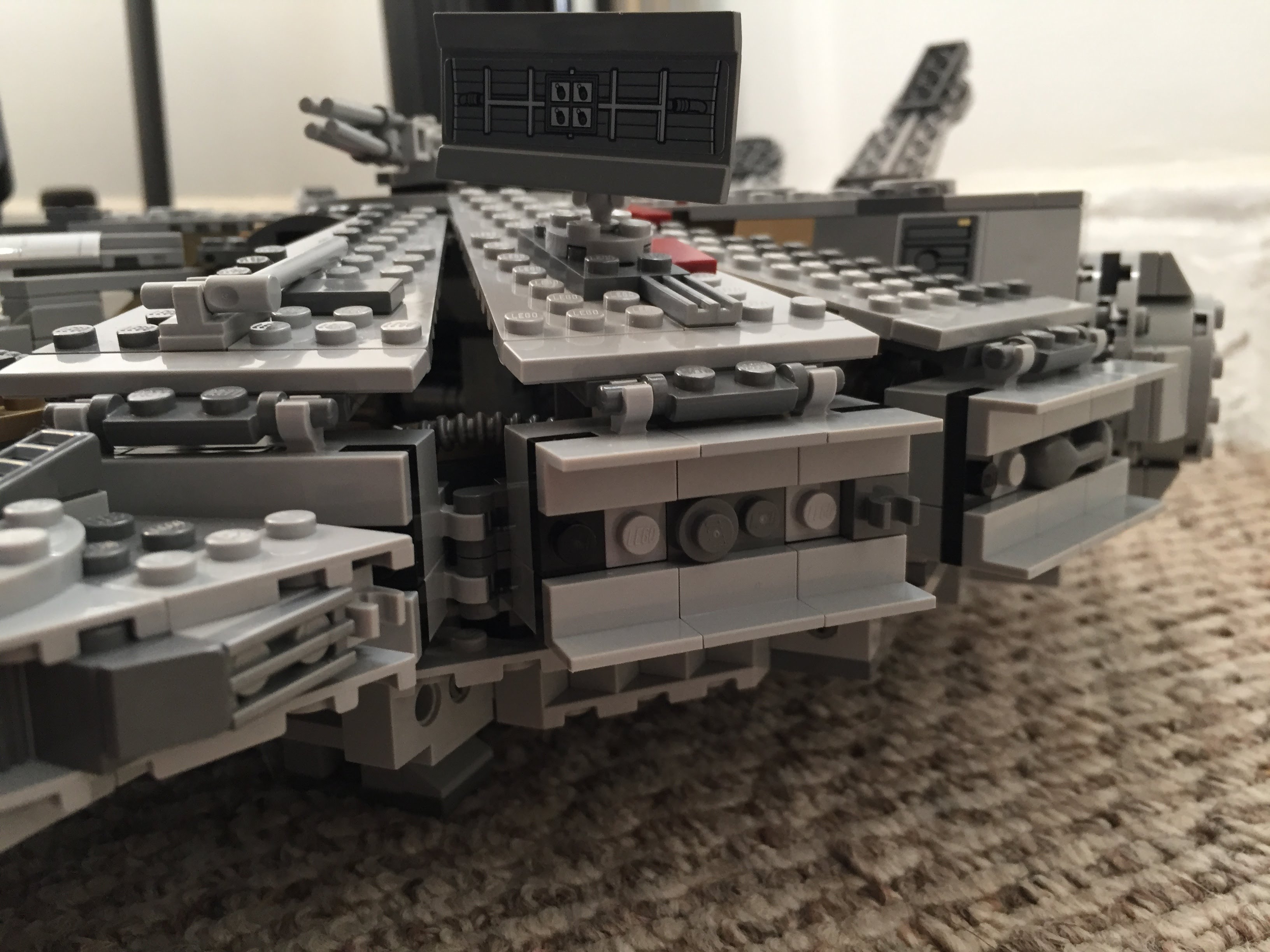
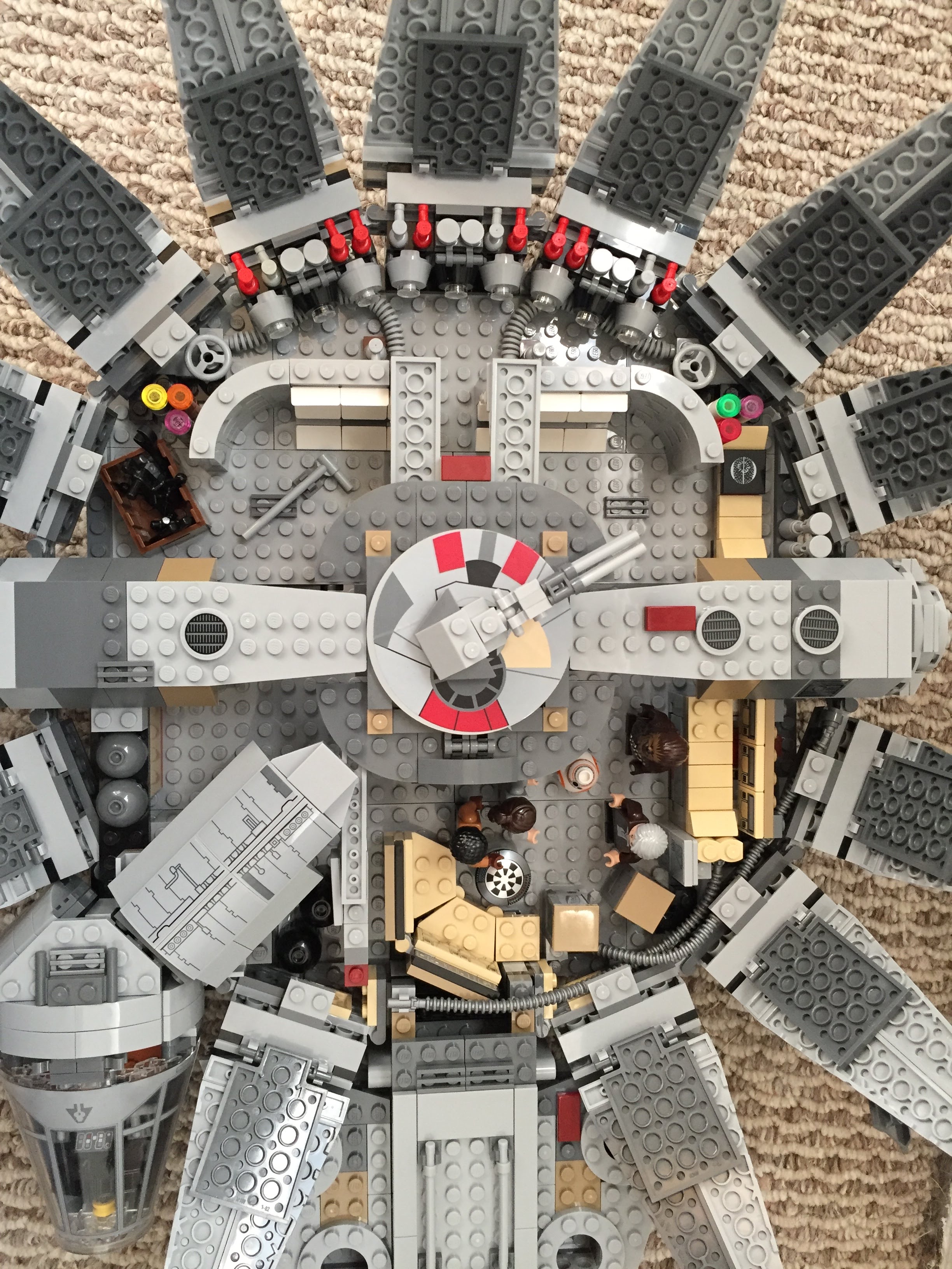
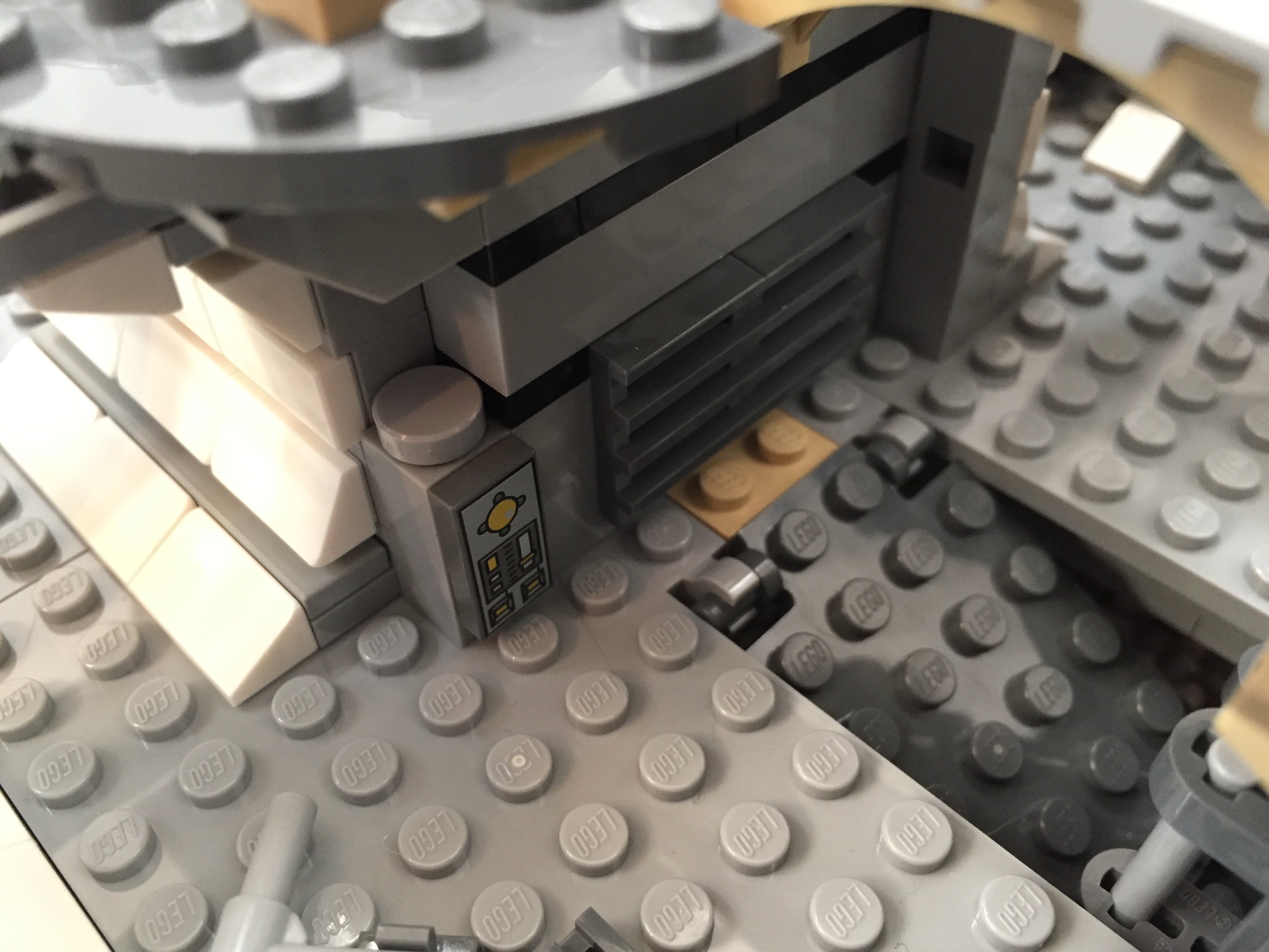
    Even with my Intel NUC PC taking very little space on my desk, I felt overrun by my LEGO creations: Hogwarts Castle in the back, Rogue One scenes in the front, and Iron Man’s Hall of Armor to the right.

    My LEGOs took the most amount of desk area, so I made it my goal to move them above my workspace onto a new shelf that I would build with materials acquired from the Brooklyn Lowes.

    My IKEA table top measures 47 3/16″ wide  and 23 1/2″ deep. I wanted my new shelf to be high enough to clear my HP 22″ LCD monitor and tabletop lamp. I figured 24″ height would be enough clearance. Also, I wanted it to be deep enough to hold my LEGO models but not deep enough that it excessively shaded my desk or posed a problem for my forehead. So, I figured 10″ depth for the shelf was good enough.

    IMG_1811

    At Lowes, I purchased a 1″ x 10″ x 48″ pine board (to make the shelf supports), 1″ x 10″ x 48″ pine board (to serve as the shelf), 4-pack brackets (to support the shelf against the supports and the supports against the IKEA table top), and 4-pack braces (to affix the shelf’s supports to the IKEA table top). The total cost for these materials was about $16. Also, I used four deck screws that I had on-hand.

    A note about selecting the shelf: If you’re doing this on the cheap like me, your selection of wood can serve in your favor. What I mean by this is that instead of building a shelf with some kind of support underneath it to prevent warping due to the weight of what you place on it over time, you can select a warped board and use the warp in your favor. To do this, find a board that is not overly warped but has some warp in its breadth. When building your shelf, have the warp pointing upward. Of course, running a support under the shelf and affixed to the shelf support on either side will strengthen the shelf to hold more weight, but with a light duty shelf like I am building, I chose to save the material and money.

    The 1″ x 10″ x 48″ pine board was actually 47 15/16″ long, which meant that it would overhang my desk by 12/16″, so I split the difference and marked the shelf supports 6/16″ or 3/8″ from either end of the shelf. Also, instead of centering the shelf supports, I placed them at the rear of the desk and the rear of the shelf. Again, this is a light duty installation, so I didn’t think this would become unstable with how I planned to use it.

    Next, I cut the shelf supports out of the 1″ x 4″ x 48″ pine board. Surprisingly, it was 47 15/16″ long, which is closer than 48″ than I expected. To cut it in half as accurately as possible, I took my miter box saw width into consideration with planning my cut. As you can see below, I wrote on the board which side to cut on to offset the board’s odd measurement.

    IMG_1812

    The next step was affixing the supports to the shelf using deck screws that I already had on hand. Of course, pine is soft wood, but there is still the possibility of splitting it, so I pre-drilled four holes in the shelf (two on either end for each support) and two holes in the top of each shelf support. Before drilling, I drew a box on the shelf bottom for each support’s location. I halved this lengthwise and then marked 1″ from either end for my drill/screw locations. I did the same for the ends of each support board so that the holes would line up when I drove in the screws.

    The final step of completing the shelf and shelf supports assembly before installing it on the IKEA table top involved installing two metal brackets to prevent shelf sway. These came with tiny philips-head screws, so I took a risk and did not pre-drill holes for these.

    IMG_1837

    Finally, I installed the shelf assembly on top of the IKEA table top using four braces and two brackets. Each shelf support received two braces on the outside, and one bracket on the inside, centered. Again, I did not pre-drill holes in the IKEA table top or the pine board. I figured that the IKEA table top has a honeycomb structure inside with only parts of it being reinforced for the table legs and frame. I hoped that there would be enough material for the screws to dig into, and it seems to have been the case. However, I had to up the RPMs on my cordless drill to get the screws started and through the laminate covering the IKEA table top.

    With the construction phase completed, I was able to begin enjoying my new shelf resting above my desk.

    IMG_1834

    And move my LEGO models into their new home.

    IMG_1836

    The making, of course, didn’t end there. In parallel, Y and I took pictures of my building progress. Then, I began writing this blog post and embedding the photos to share with others (another form of making). Maybe now, you will go make something of your own!

  • Updated and Expanded LEGO Iron Man’s Hall of Armor

    IMG_1735

    While continuing to sort my LEGO brick collection, I discovered four more Plate (A) 4M 45° pieces. With these special elements in-hand, I updated and expanded my LEGO Iron Man’s Hall of Armor, which I wrote about previously here.

    IMG_1726

    I used a similar repetition for each armor suit pod, but I added one stud roof tiles (Roof Tile 1X1X2/3, Abs) at the base of each vertical transparent blue wall on either side of an armor suit.

    IMG_1728
    Armors from left to right: Mark III (Iron Man film), Mark VI (Avengers), and Mark XVII “Heartbreaker” (Iron Man 3)

    To complete the model, I needed Iron Man’s armor with the triangular arc reactor window from the first Avengers movie (Mark VI armor). I ordered the 30167 polybag on ebay from a seller in Brooklyn (interestingly, it takes longer for mail to arrive from within my city borough than it does from California or even Germany at standard postal rates!).

    IMG_1729
    Armors from left to right: Mark XVII “Heartbreaker” (Iron Man 3), Mark XLII (Iron Man 3), and Mark XLIII (Avengers: Age of Ultron).
    IMG_1730
    Armors from left to right: Mark XLIII (Avengers: Age of Ultron), Mark XLV (Avengers: Age of Ultron), and Mark XLVI (Captain America: Civil War).

    I needed to redesign the base, so I opted to give it a symmetrical support underneath and and a stairway entrance in the southward position. It connects to the circular armor pod assembly with Technics connector pegs and bricks under the northward armor pod. While the center platform makes a tight and neat fit to the upper three pods, its plate studs do not line up with the side or bottom pods (there is a slight gap of about 1/16 to 1/8 of an inch).

    IMG_1731

    It is a sturdy model that can be lifted from any point. Due to its limited interior space and the size of my adult hands, it is difficult to remove and replace the Iron Man armor in each pod.

    IMG_1733

    My next idea for the set is to elevate it by about its current height and create a crank-driven lift in the central platform for Tony Stark’s grand entrance. This will take some more planning and time. I’m sure that Ant Man will be watching my progress.

    IMG_1736