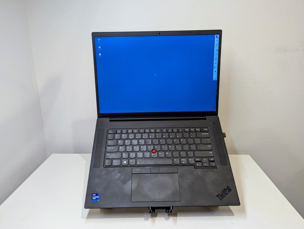
I’ve been using my Lenovo Thinkpad P1 Gen4 laptop as a desktop replacement system lately, so I wanted to raise its screen higher to avoid slouching and subsequent neck and shoulder pain. While there are lots of solutions to buy, I opted to use the LEGO Technics that I had on hand to build a stand. My goals for the project were facilitating maximum air flow and reliably holding a 4 lb. 5 oz. laptop.
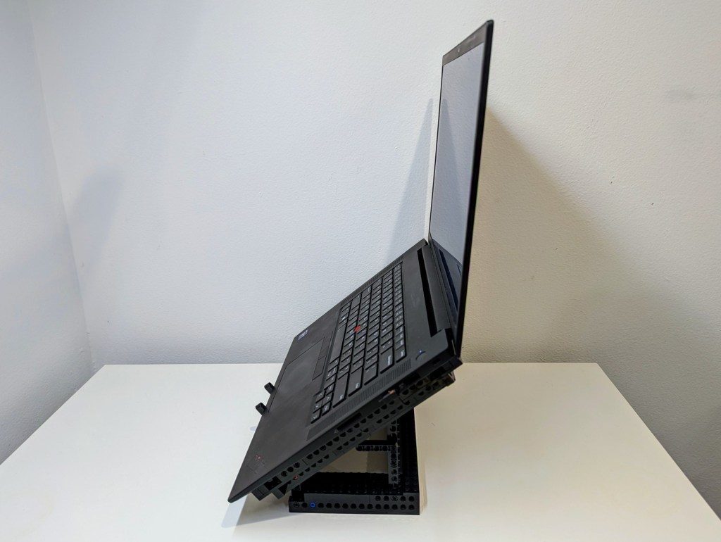
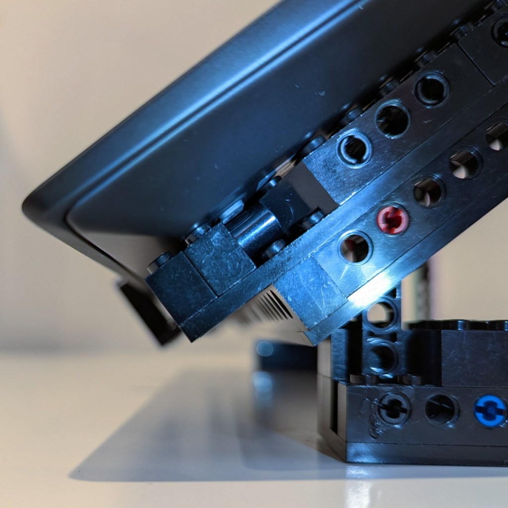
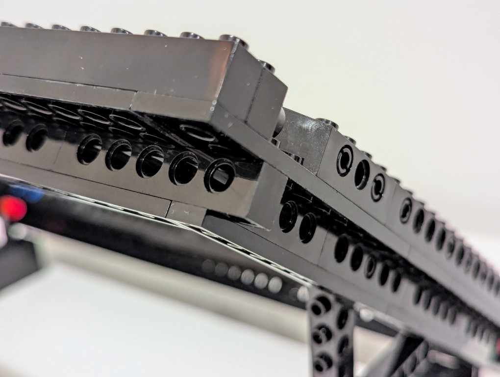
I started by disassembling the folding stand that I had built in 2024, but I noted how I sandwiched a Technic beam between two Technic bricks. The beam’s lower dimension provided a smooth shelf for the laptop’s feet to rest on and the studs on the bricks kept the laptop from sliding off the beam toward the front or rear. I planned to replicate this design in the new laptop stand.
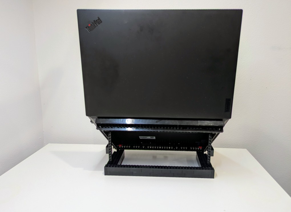
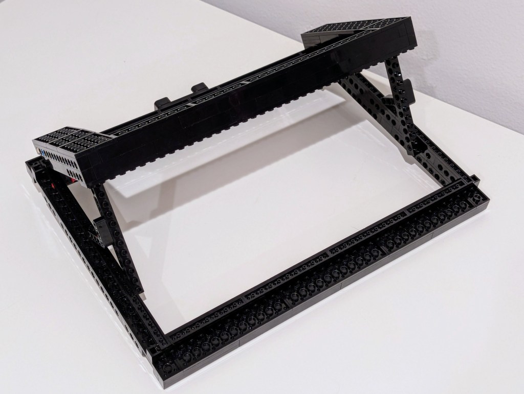
Another important element of the design was an open space beneath the laptop for maximum air flow (this laptop has an NVIDIA RTX A5000 16GB video card that I use for AI workflows). I figured that a rectangular holder for the laptop would work best and allow me to use the black Technic bricks that I had on hand in limited numbers (I have far more light and dark gray elements thanks to all of the Star Wars sets I’ve built over the years).
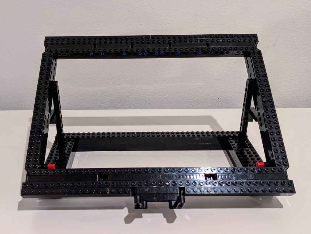

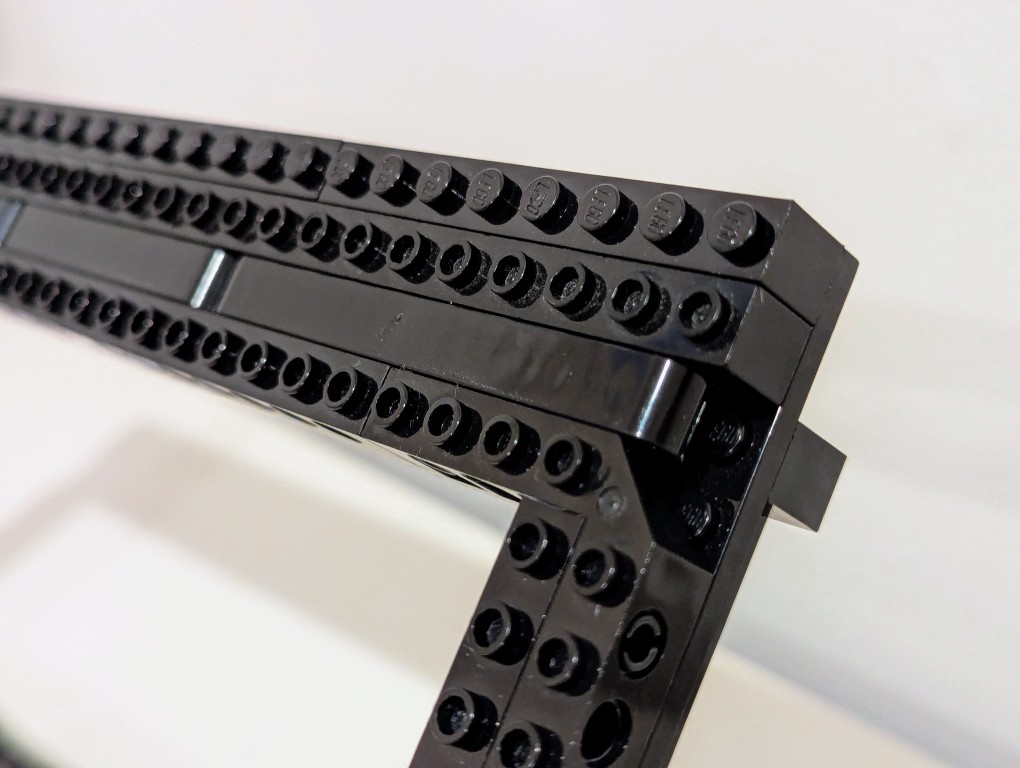
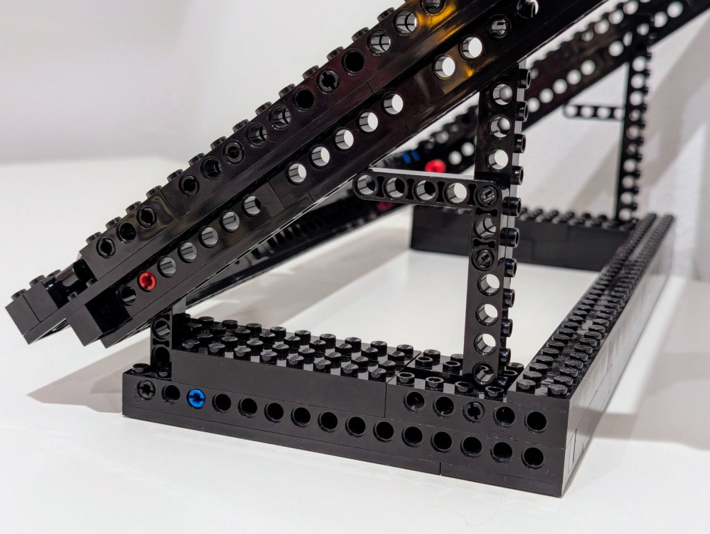
To strengthen the rectangular frame, there are four layers: top-most brick structure, plates, substructure bricks, and plates. All joints are overlapped, which further strengthens the design.
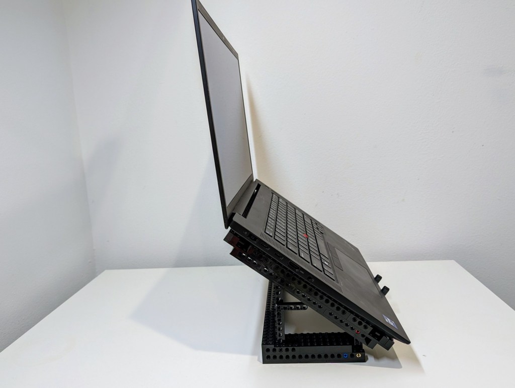
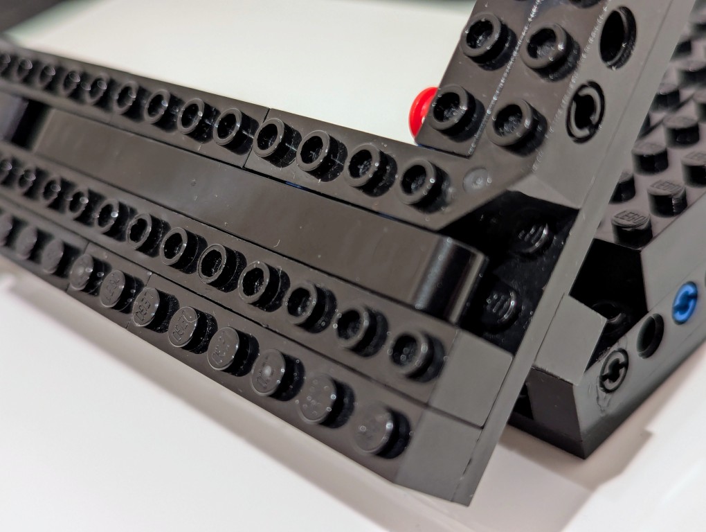
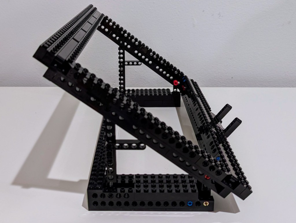
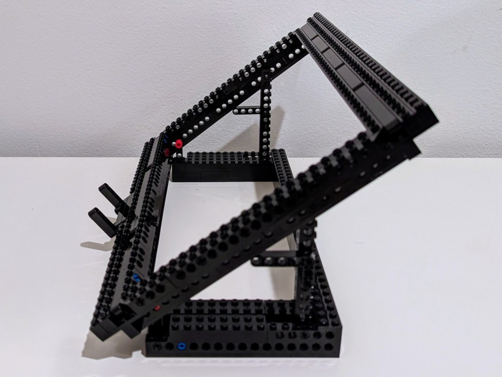
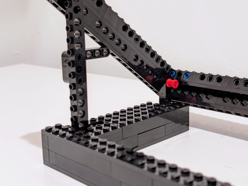
To support the rectangular laptop frame, I used one L-shaped beam to hold the frame at the bottom and a long Technic brick at 90 degrees to raise the back. As an added support to the back Technic brick, I put a L-shaped beam to apply pressure to the rectangular frame when under the weight of the laptop.
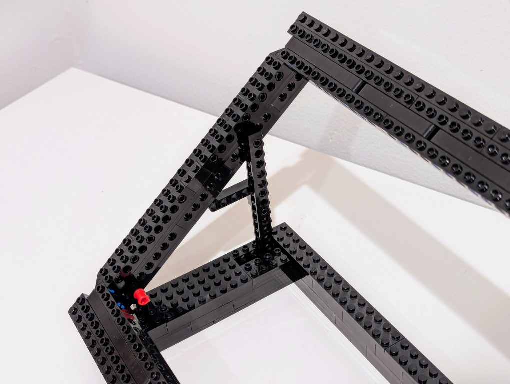
The base of the stand is U-shaped to hold either side’s base in place to prevent any lateral movement, which could cause one of the supports to unhinge.
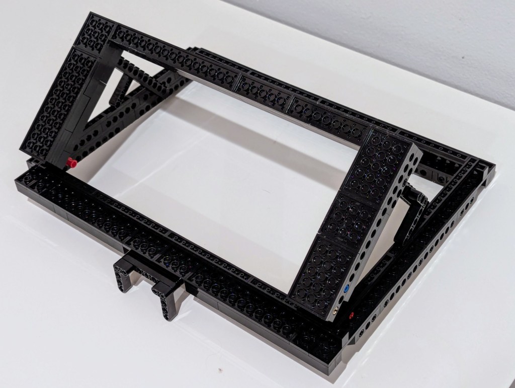
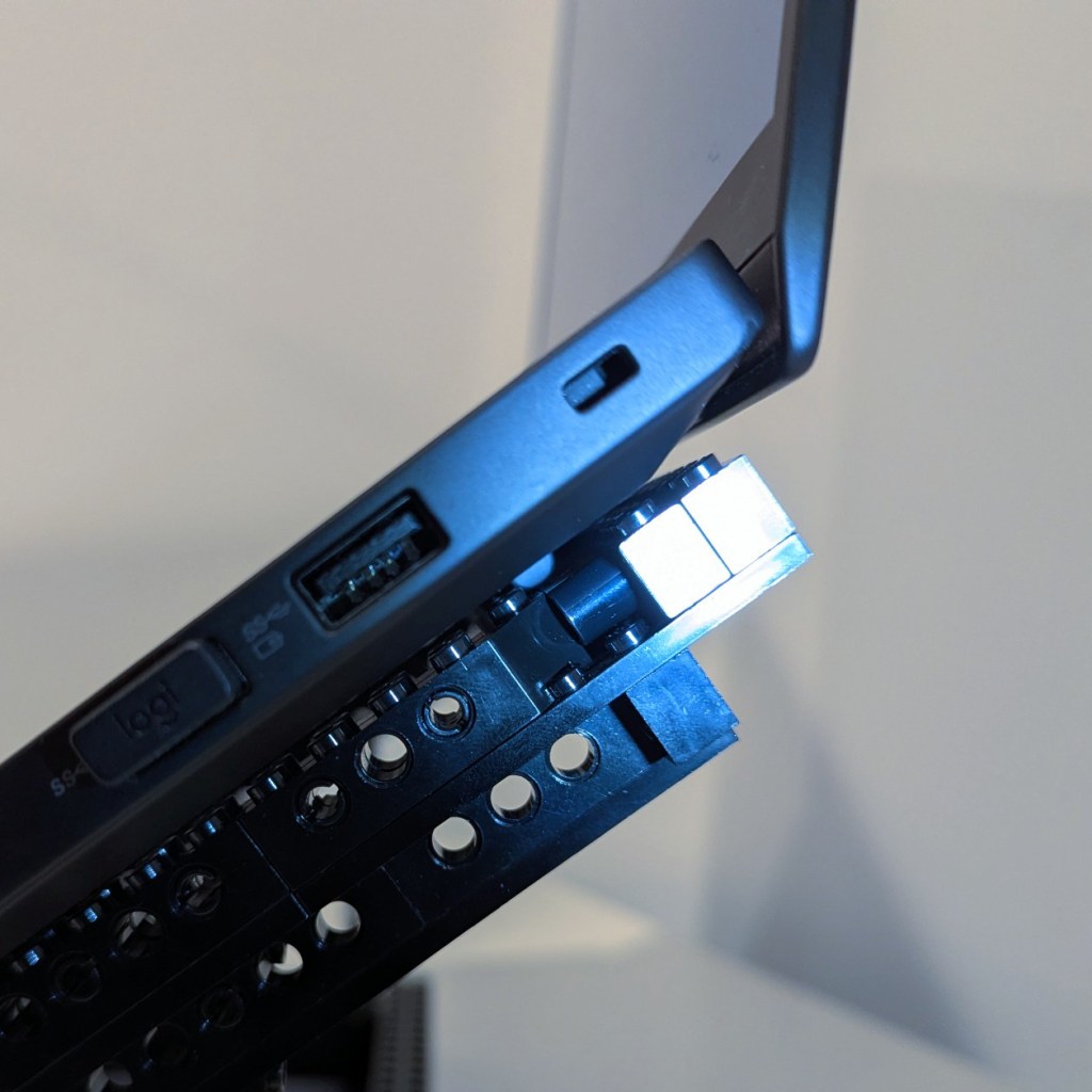
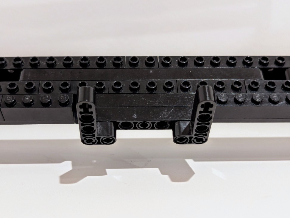
As a safety measure, I added two Technic L-shaped beams to the bottom center of the laptop frame if not to hold the laptop in place should it slip off then to slow it down as it crashes forward on my desk. I’ve also found this useful for holding paper, such as printed articles, which makes it easy to read and type by looking down-and-up instead of to the left or right.
The stand raises the back of the laptop up 7″, which makes the top of the monitor about even with my eye line. I’ve only been using it a couple of days, but it seems to fit the bill perfectly for my needs.