I believe that it is important for everyone to make things. Making uses the brain and the body. Making acts on the world. Making is an expression of ourselves. Making can be for ourselves alone or it can be shared with others. Making can be meta, too–making about making (like this blog post). Making in all of its forms is a really big part of what makes us human.
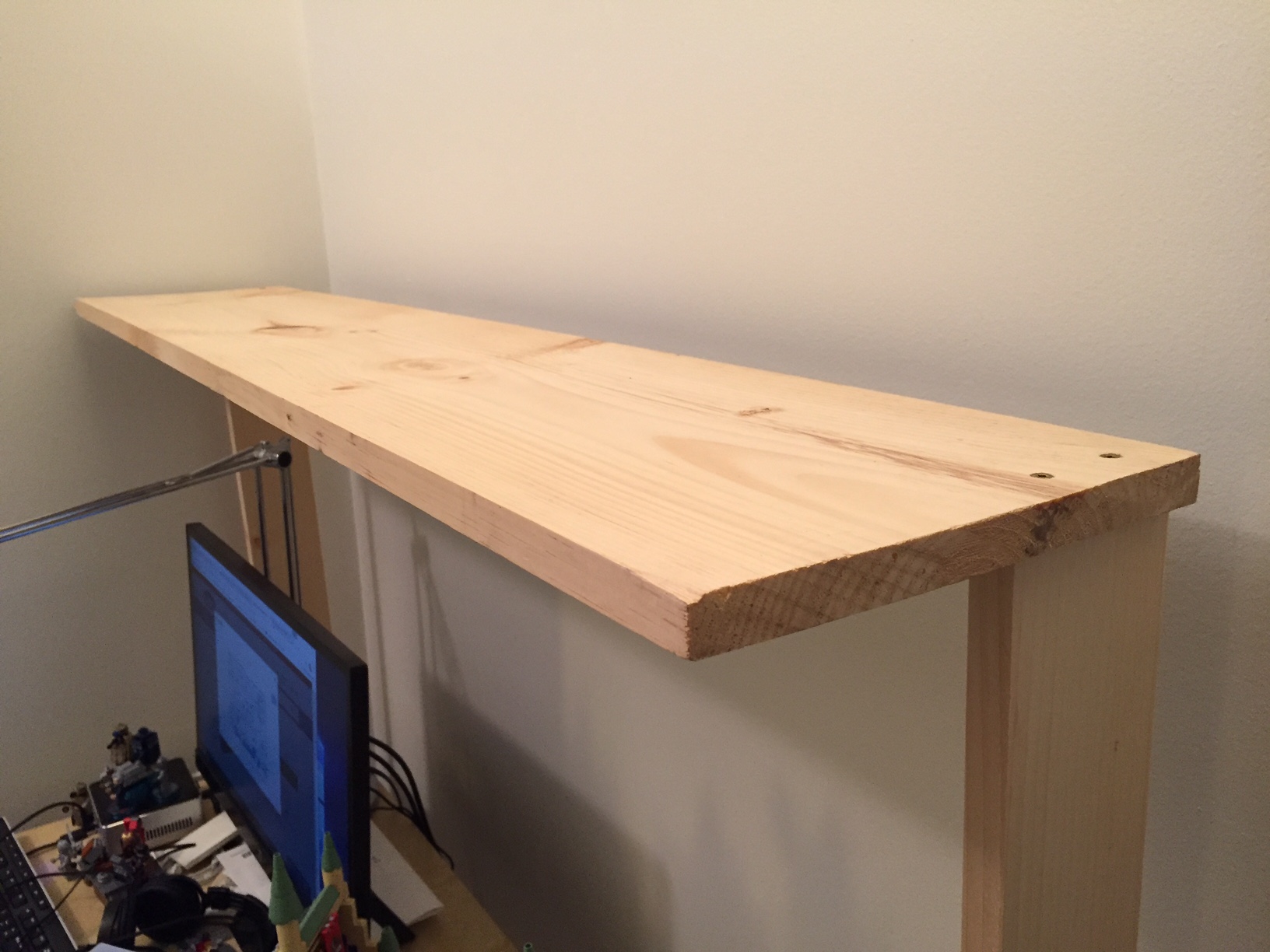
Doing a bit of making today, I built a raised shelf for my IKEA table top desk using pine boards. It began as a thing for myself, and it continues as a thing shared with you here.
I like working with wood. Unfortunately, I don’t get to build things with wood as often as I would like. When I lived in Atlanta, I had space and tools. Here in New York, I have little of the former and few of the latter. Nevertheless, I find small ways to stay in the woodworking game by building things to solve problems such as the state of my work-at-home desk:
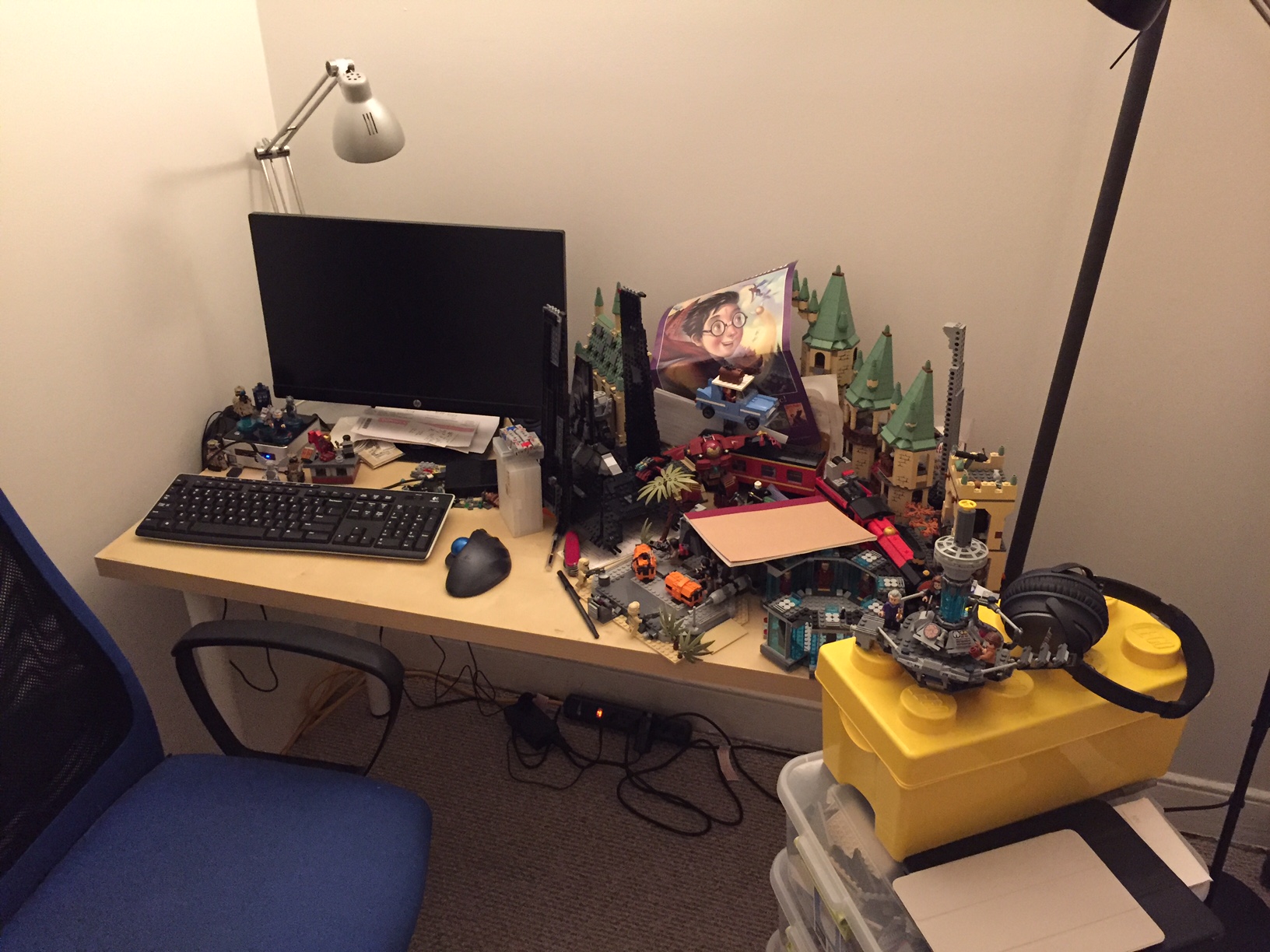
Even with my Intel NUC PC taking very little space on my desk, I felt overrun by my LEGO creations: Hogwarts Castle in the back, Rogue One scenes in the front, and Iron Man’s Hall of Armor to the right.
My LEGOs took the most amount of desk area, so I made it my goal to move them above my workspace onto a new shelf that I would build with materials acquired from the Brooklyn Lowes.
My IKEA table top measures 47 3/16″ wide and 23 1/2″ deep. I wanted my new shelf to be high enough to clear my HP 22″ LCD monitor and tabletop lamp. I figured 24″ height would be enough clearance. Also, I wanted it to be deep enough to hold my LEGO models but not deep enough that it excessively shaded my desk or posed a problem for my forehead. So, I figured 10″ depth for the shelf was good enough.
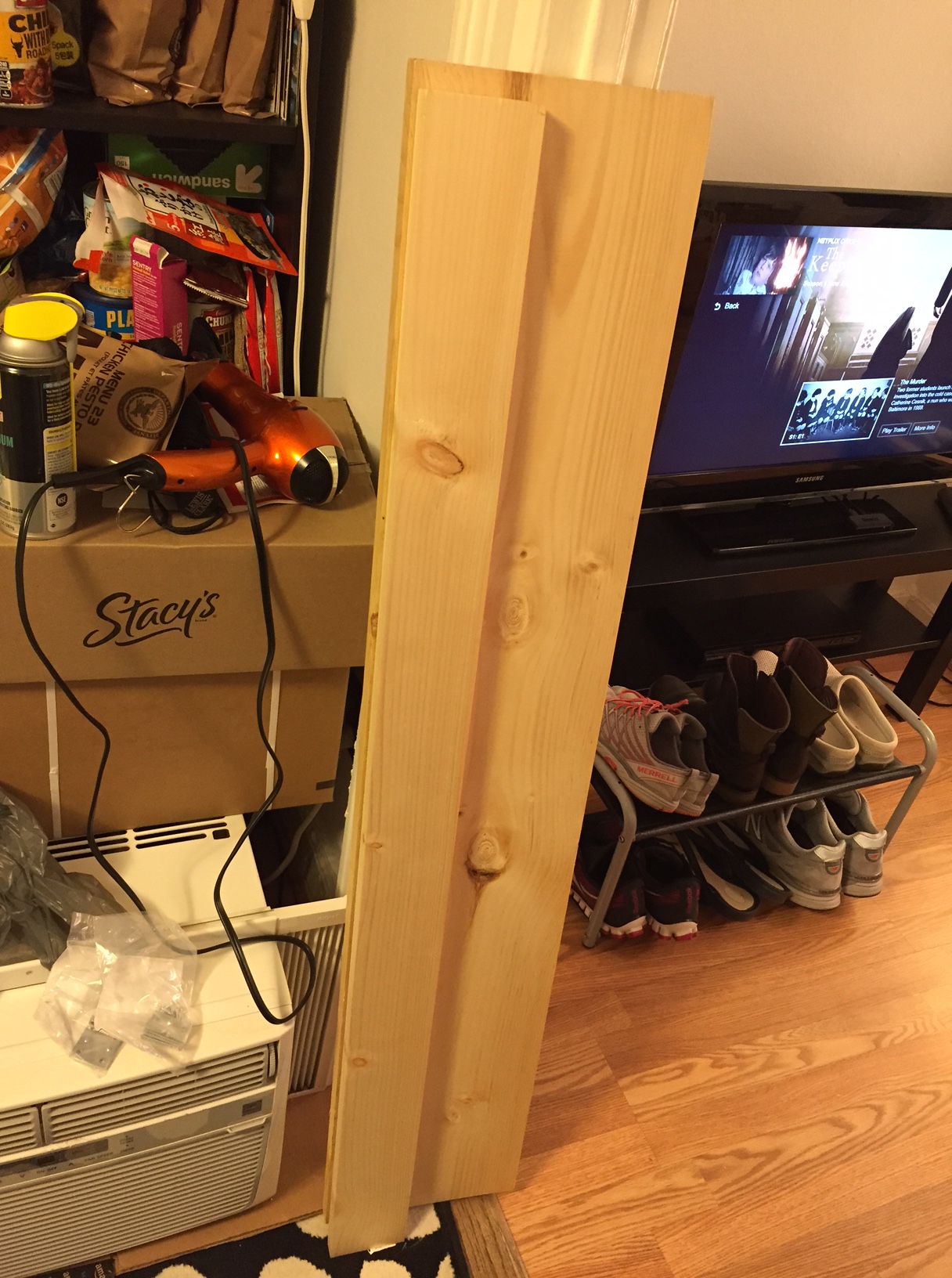
At Lowes, I purchased a 1″ x 10″ x 48″ pine board (to make the shelf supports), 1″ x 10″ x 48″ pine board (to serve as the shelf), 4-pack brackets (to support the shelf against the supports and the supports against the IKEA table top), and 4-pack braces (to affix the shelf’s supports to the IKEA table top). The total cost for these materials was about $16. Also, I used four deck screws that I had on-hand.
A note about selecting the shelf: If you’re doing this on the cheap like me, your selection of wood can serve in your favor. What I mean by this is that instead of building a shelf with some kind of support underneath it to prevent warping due to the weight of what you place on it over time, you can select a warped board and use the warp in your favor. To do this, find a board that is not overly warped but has some warp in its breadth. When building your shelf, have the warp pointing upward. Of course, running a support under the shelf and affixed to the shelf support on either side will strengthen the shelf to hold more weight, but with a light duty shelf like I am building, I chose to save the material and money.
The 1″ x 10″ x 48″ pine board was actually 47 15/16″ long, which meant that it would overhang my desk by 12/16″, so I split the difference and marked the shelf supports 6/16″ or 3/8″ from either end of the shelf. Also, instead of centering the shelf supports, I placed them at the rear of the desk and the rear of the shelf. Again, this is a light duty installation, so I didn’t think this would become unstable with how I planned to use it.
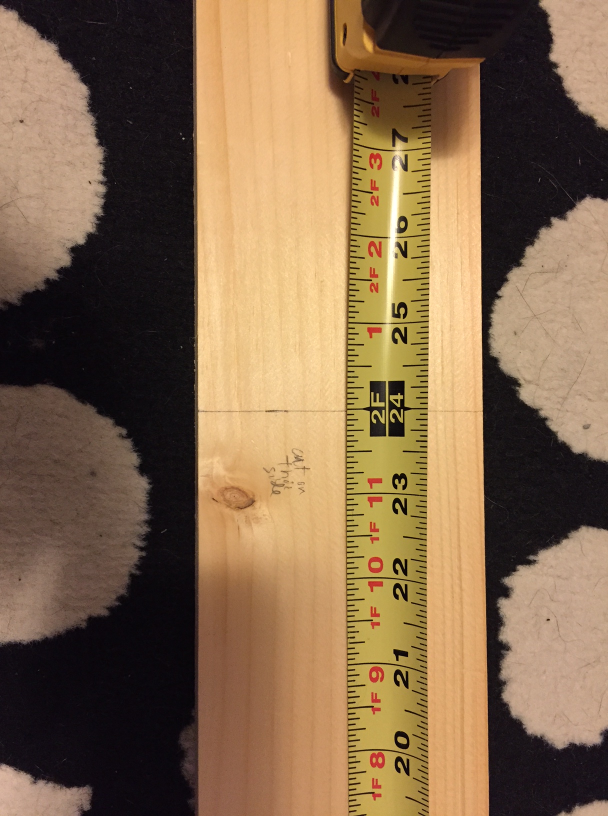
Next, I cut the shelf supports out of the 1″ x 4″ x 48″ pine board. Surprisingly, it was 47 15/16″ long, which is closer than 48″ than I expected. To cut it in half as accurately as possible, I took my miter box saw width into consideration with planning my cut. As you can see below, I wrote on the board which side to cut on to offset the board’s odd measurement.
The next step was affixing the supports to the shelf using deck screws that I already had on hand. Of course, pine is soft wood, but there is still the possibility of splitting it, so I pre-drilled four holes in the shelf (two on either end for each support) and two holes in the top of each shelf support. Before drilling, I drew a box on the shelf bottom for each support’s location. I halved this lengthwise and then marked 1″ from either end for my drill/screw locations. I did the same for the ends of each support board so that the holes would line up when I drove in the screws.
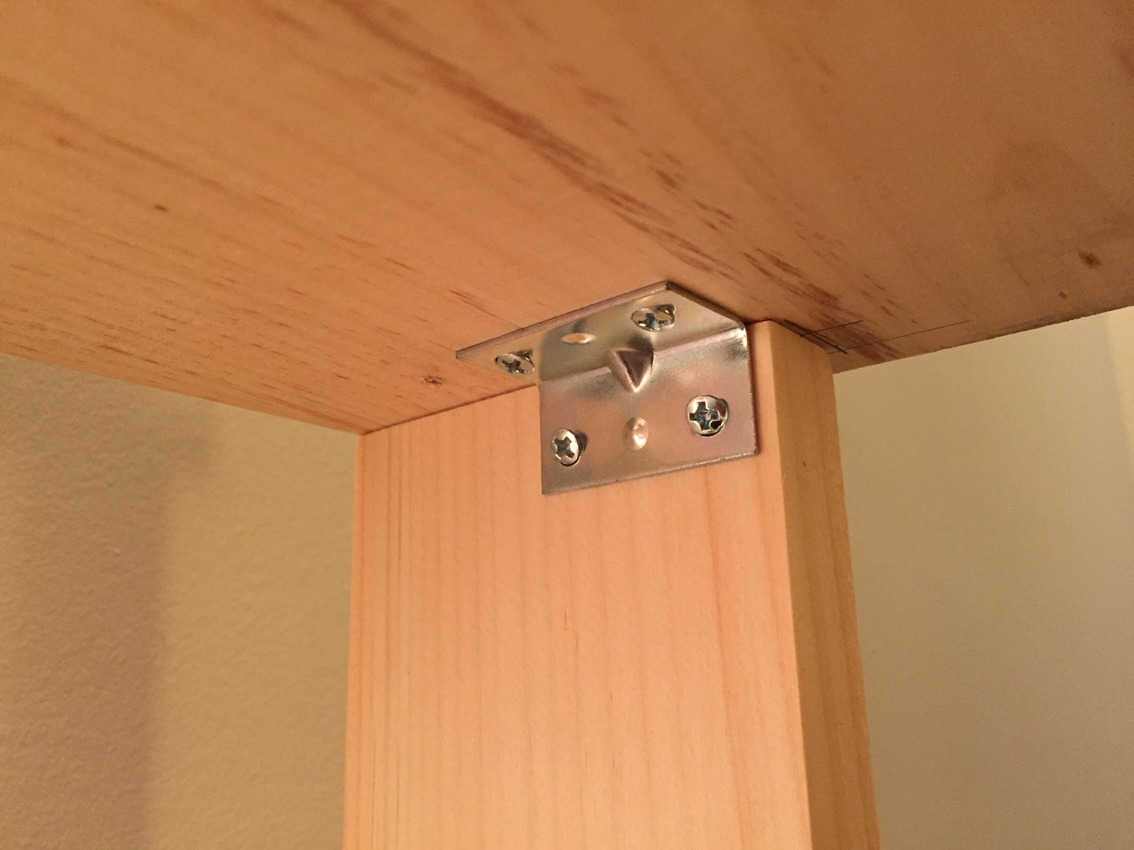
The final step of completing the shelf and shelf supports assembly before installing it on the IKEA table top involved installing two metal brackets to prevent shelf sway. These came with tiny philips-head screws, so I took a risk and did not pre-drill holes for these.
Finally, I installed the shelf assembly on top of the IKEA table top using four braces and two brackets. Each shelf support received two braces on the outside, and one bracket on the inside, centered. Again, I did not pre-drill holes in the IKEA table top or the pine board. I figured that the IKEA table top has a honeycomb structure inside with only parts of it being reinforced for the table legs and frame. I hoped that there would be enough material for the screws to dig into, and it seems to have been the case. However, I had to up the RPMs on my cordless drill to get the screws started and through the laminate covering the IKEA table top.
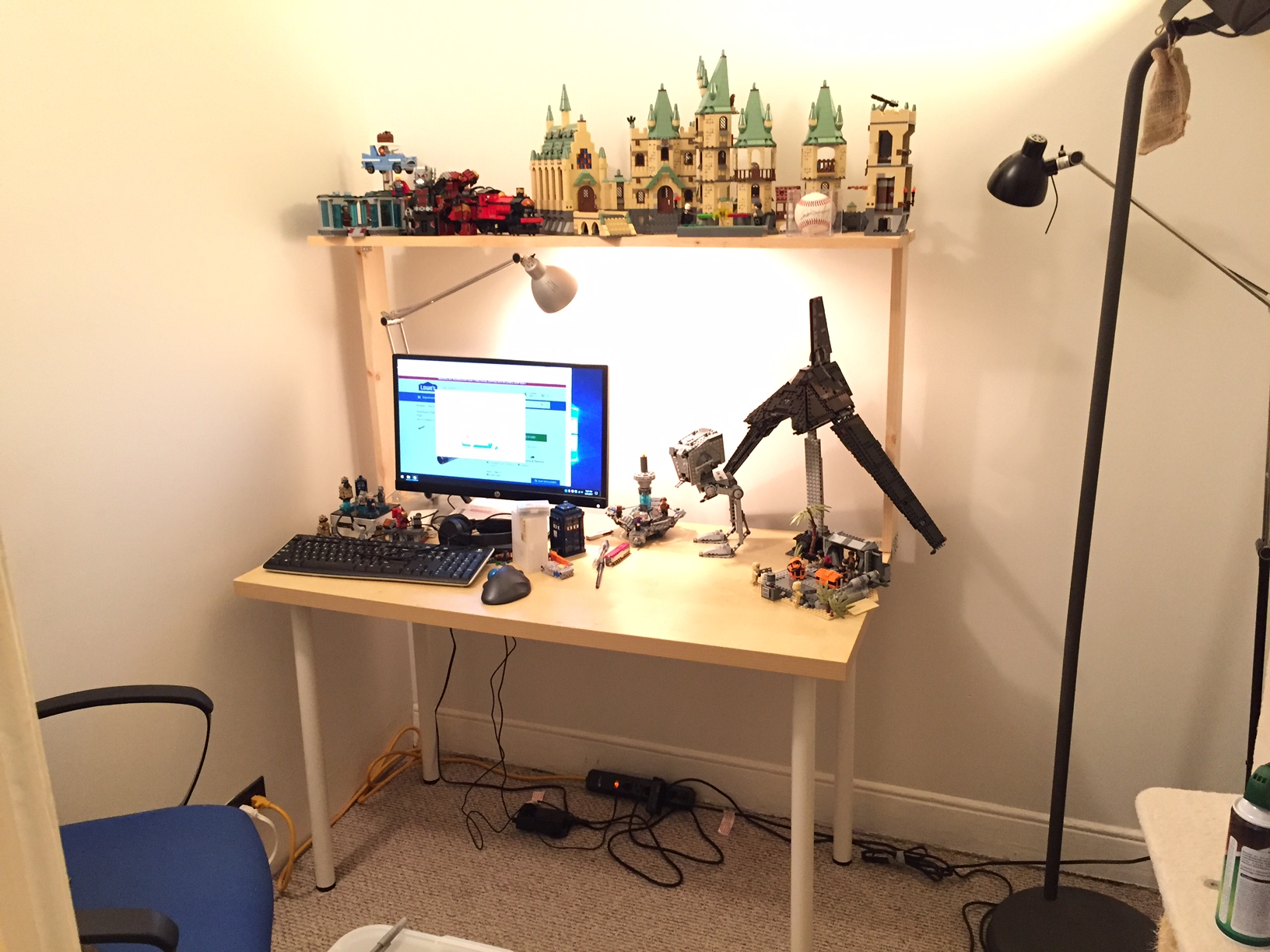
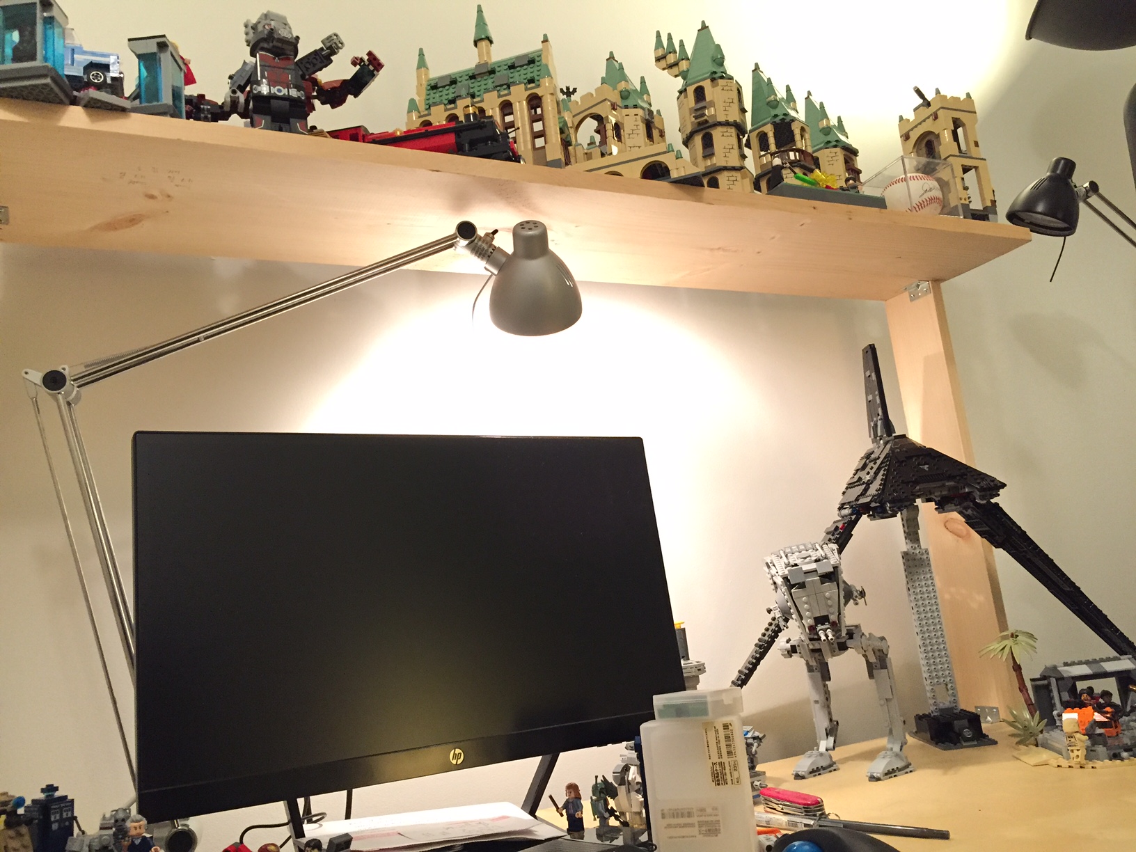
With the construction phase completed, I was able to begin enjoying my new shelf resting above my desk.
And move my LEGO models into their new home.
The making, of course, didn’t end there. In parallel, Y and I took pictures of my building progress. Then, I began writing this blog post and embedding the photos to share with others (another form of making). Maybe now, you will go make something of your own!
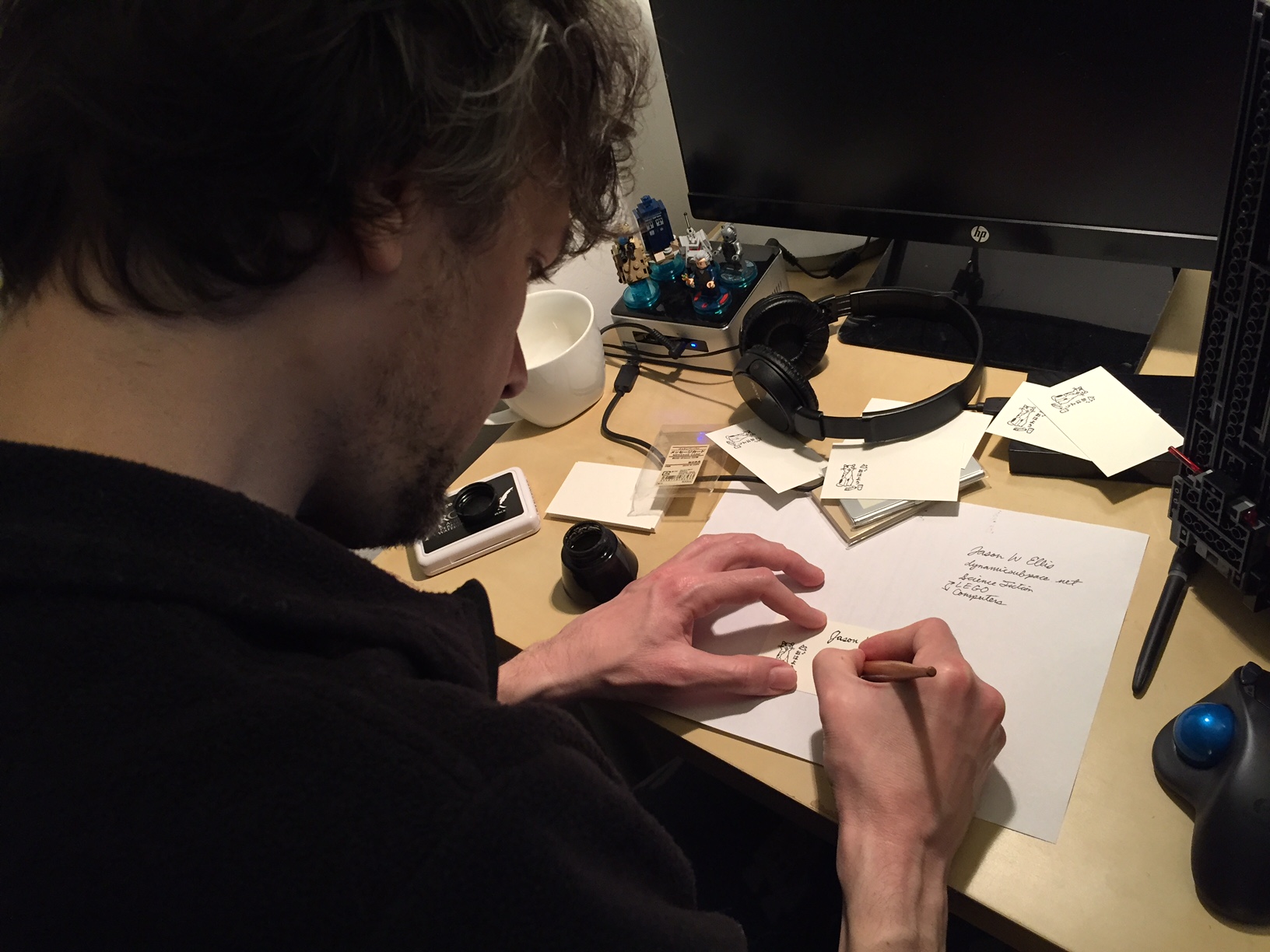
This Saturday afternoon, I wanted to make something useful by doing something fun, so I made a small batch of custom business cards using a rubber stamp and one of Y’s nib or dip pens.
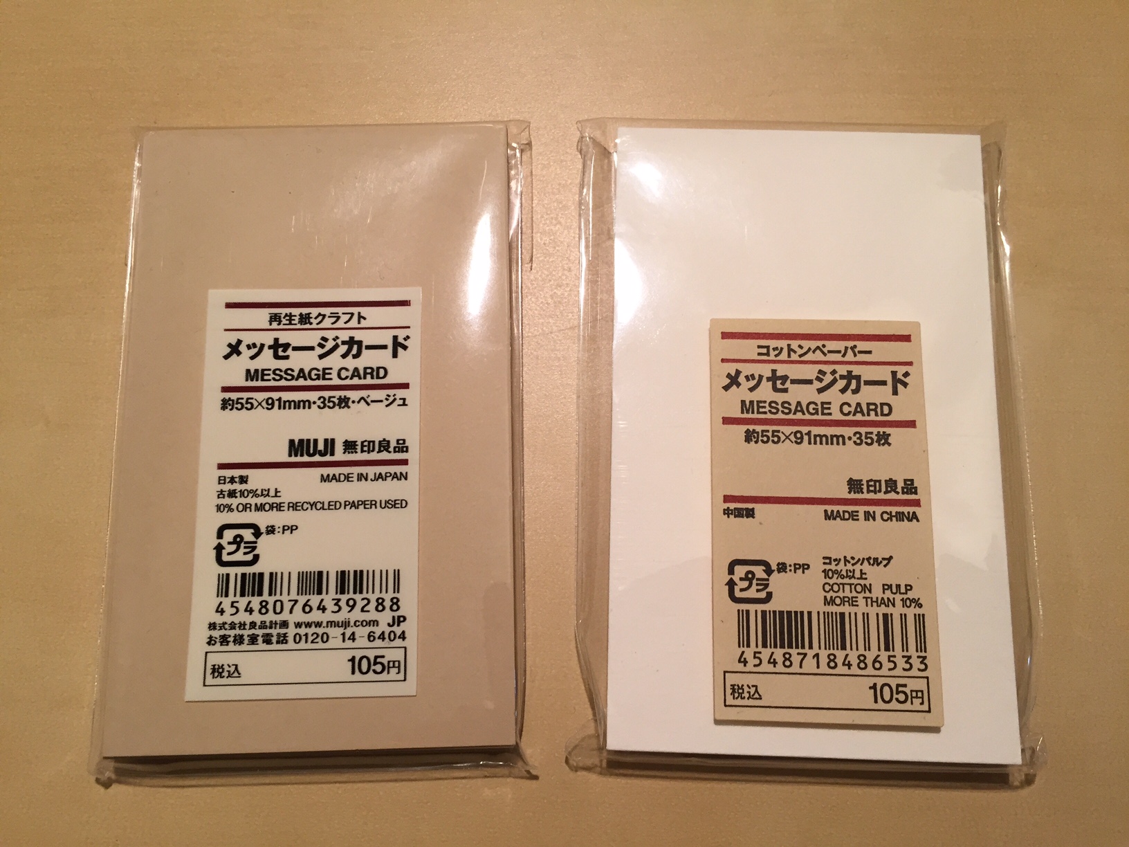
First, I assembled the materials for my business cards. I picked up “Message Card” packs in white and kraft from Muji in Manhattan.
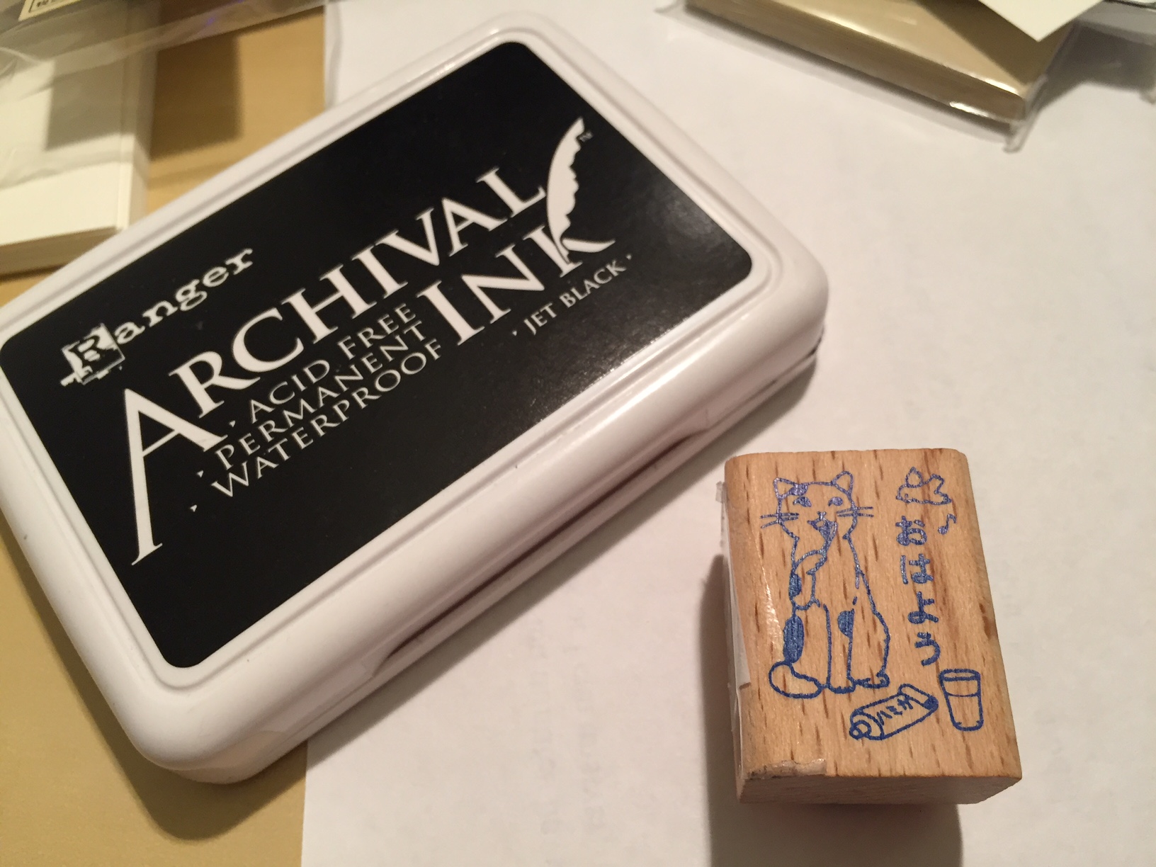
Next, I found a cute neko hanko/pottering cat rubber stamp that I liked at Kinokuniya by Bryant Park. This particular rubber stamp shows a cat brushing his teeth with the message おはよう (prounounced as ohayo), and translated as “good morning.” (NB: Y told me that the trick to properly inking the stamp is to hold the ink pad upside down and bring the stamp into contact with the pad from below in an upward motion–tap tap tap.)
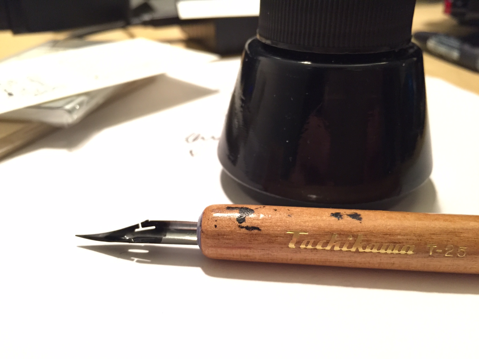
Since I wanted to write each card’s message by hand, I figured that using a dip pen would lead to a more interesting end product due to my being a novice using that kind of pen. I knew that there would be more variability with my writing than if I used a ball point pen, which is the look that I wanted each business card to have. (NB: Y instructed me to dip the nib into the ink well and then to dab off excess ink on the rim of the ink well before beginning to write.)
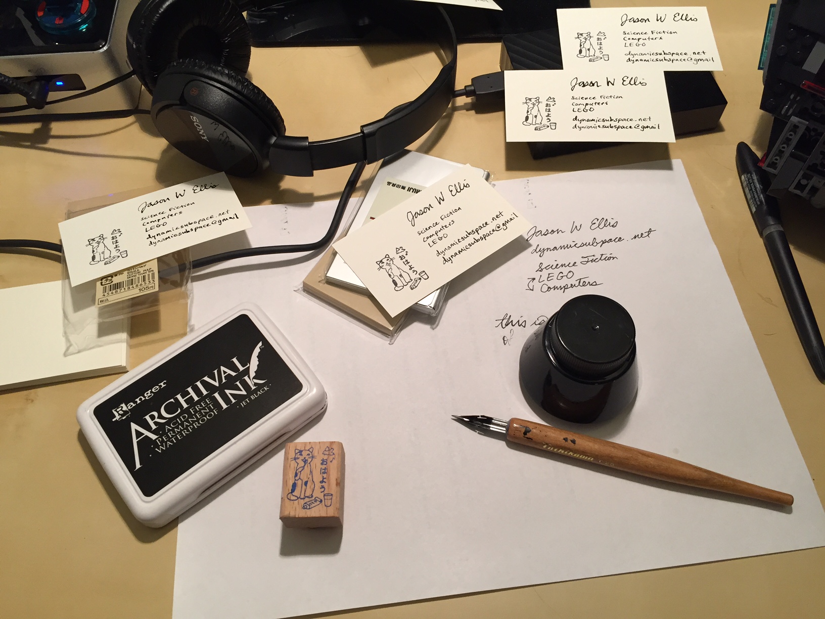
With my materials gathered, I cleared a bit of desk space and put a scrap piece of paper down to catch any stray ink from the ink pad and stamp or the ink well and nib pen. Also, I used the scrap paper to plan out what exactly I wanted to write on each business card, which in this case was:
Jason W. Ellis
Science Fiction
Computers
LEGO
dynamicsubspace.net
dynamicsubspace@gmail
With this first batch, I made ten business cards to give out to special contacts. Each card is slightly different. Because each is handmade, each card is unique. Perhaps this uniqueness and care put into each card will itself represent something important about me and my work ethic to those persons who receive one of these cards.
Also, I found this work to be enjoyable and relaxing. Inking the stamp, pressing the stamp, dipping the pen into ink, dabbing excess ink on the edge of the ink well, carefully writing with the nib are all satisfying activities. I found stamping and handwriting to be pleasurable during the act of making the cards. It was gratifying to see the finished cards peppered all over my desk.
I delivered this presentation at the James Madison University Pulp Studies Symposium on October 7, 2016. The script of my talk is included below.
The paper is about introducing new audiences to old ideas for the benefit of two different City Tech audiences: 1) frame the historical publication context of science fiction short stories for students, and 2) illuminate the deep history of technological ideas for faculty fellows in the NEH-funded “Cultural History of Digital Technology” project.
[UPDATE: The symposium was a great success! Thank you to everyone who had questions and comments during our session. I posted photos taken by colleague Caroline Hellman over at the Science Fiction at City Tech website.]
Engagement, Learning and Inspiration in SF: Use Cases for the City Tech Science Fiction Collection
Jason W. Ellis
In the first issue of Amazing Stories dated April 1926, Hugo Gernsback writes:
By ‘scientifiction’ I mean the Jules Verne, H. G. Wells and Edgar Allan Poe type of story—a charming romance intermingled with scientific fact and prophetic vision … Not only do these amazing tales make tremendously interesting reading—they are always instructive. (Gernsback 3)
According to Gernsback, the literary genre that would become known as science fiction combines romance, scientific fact, and prophetic vision. The romance engages the reader in an interesting story. The facts instruct the reader in science and technology. The prophetic vision extrapolates from what is known into the not-yet-known and simultaneously inspires readers to realize that vision. I believe that Gernsback’s vision of SF is fundamental to arguments for SF collections at colleges with a pedagogical and community-serving commission like City Tech. Our college occupies several buildings in downtown Brooklyn and serves the educational needs of over 17,000 students. Historically a trade and vocational school, it has over time and by design developed into a senior college of the City University of New York (CUNY) system. Nevertheless, the students it serves and the fields it attempts to prepare them for are primarily focused on STEM career paths. While not all stakeholders recognize the importance that the humanities have to STEM graduates’ success and overall outlook, the administration’s support of the City Tech Science Fiction Collection signals at least one way in which the humanities—in this case via SF—is seen as supportive to the otherwise STEM-focused educational work of the college. In effect, SF and the collection serves as a source for engagement, learning, and inspiration for students who have much to gain from it as a literary genre that reveals the inextricable linkages between STEM and the humanities. While I cannot within the scope of this presentation explore all of these functions of SF, I will restrict myself to discussing how I have used the collection to support my teaching and pedagogical work at City Tech.
Teaching Science Fiction from a Historical Perspective
For students, my SF syllabus takes a historical approach to the genre. Following Brian Aldiss, I point to Mary Shelley’s Frankenstein as the genre’s beginning, because its plot pivots upon on an extrapolation of science and technology. Following this novel, I have students read a chronological progression of short stories that correspond with the movements in the genre: proto-science fiction and SF’s influences, H.G. Wells and his scientific romances, Jules Verne and his Voyages extraordinaires, Hugo Gernsback’s scientifiction and the pulps, John W. Campbell, Jr. and the Golden Age, the New Wave, Feminist SF, Cyberpunk, and contemporary SF. Looking at my current syllabus, which draws on readings from the Wesleyan Anthology of Science Fiction and a few stories in PDF form that are not in the anthology, over half appear for the first time in magazines held in the City Tech Science Fiction Collection, including: Isaac Asimov’s “Reason,” Astounding Science Fiction, April 1941; Tom Godwin’s “The Cold Equations,” Astounding Science Fiction August 1954; Robert Heinlein’s “All You Zombies—,“ The Magazine of Fantasy and Science Fiction, March 1959; Harlan Ellison’s “Repent, Harlequin! Said the Ticktockman,” Galaxy Magazine, December 1965; Philip K. Dick’s “We Can Remember It For You Wholesale,” The Magazine of Fantasy and Science Fiction April 1966; James Tiptree, Jr’s “The Women Men Don’t See,” The Magazine of Fantasy and Science Fiction December 1973; William Gibson’s “Burning Chrome,” Omni July 1982; and Octavia Butler’s “Speech Sounds,” Isaac Asimov’s Science Fiction Magazine Mid-December 1983. In addition to discussing each story in its historical context and its addressing Gernsback’s tripartite definition (along with other definitions, too), I show students photos of the magazines and their contents. I relate how these magazines were a big deal that introduced readers to engaging stories, new science and technology, and inspirational ideas via the haptic and tactile experience of reading printed magazines. Furthermore, the contents of a given magazine add an anthropological context to the magazines via editorials, letters, fandom, and advertising. Finally, the magazines help situate the readings for students, because they empower me to point at the library and take the readings out of the abstract realm of anthologization.
NEH-sponsored “Cultural History of Digital Technology” Project
While my students’ experience of SF is enriched by the historical materiality of our readings, City Tech’s faculty, who are engaged in pedagogical planning that bridges STEM and the humanities, share some of the same needs as my students. I have learned that my STEM-focused colleagues are experts in their fields, but many do not conceptualize SF on one level as a literary genre that addresses Gernsback’s tripartite definition: romance, scientific facts, and prophetic vision, or on another level as a literary form built on interdisciplinary STEM methodologies (i.e., building assemblages of ideas and constructing extrapolations) and focused on the effects of science and technology on humanity and vice versa (e.g., Asimov’s concept of “social science fiction” or Philip K. Dick’s epistemological and ontological adventures). Professor Anne Leonhardt of Architectural Technology and director of the NEH-funded project titled, “The Cultural History of Digital Technology: Postulating a Humanities Approach to STEM,” asked me to join and contribute my humanities-focused perspective. The project’s goal is to create six interdisciplinary pedagogical modules—on maps, fractals, robotics and sociality, geotagging, topology, and finally, robotics and the workplace. We do this by inviting speakers, holding reading groups, and participating in pedagogical workshops. The student-facing modules will integrate readings, classroom lecture and demonstration, and a hands-on activity. Initially, I helped with finding readings for two modules—fractals and topology, but as I describe below, I have leveraged the City Tech Science Fiction Collection’s magazine holdings and demonstrated that humanities folks can do more than find interesting readings. Also, I will use Gernsback’s definition as a measure of each considered story’s usefulness to the module’s goals.
3D Printing
The first module that I contributed readings to is called “Fractals: Patterning, Fabrication, and the Materiality of Thinking.” Its purpose is to bridge students’ understanding of mathematics to the natural world by using fractal geometry—the notion that Benoit Mandelbrot introduced as the process and principle of order and structure underlying the physical world. We teach students the underlying principles of fractal geometry, help them create a workflow using open-source tools to generate a 3D printable STL, or STereoLithography model, and finally, have them print their model using one of City Tech’s powder or plastic 3D printers.
Initially, I did not consider the City Tech Science Fiction Collection’s holdings, because everything was sitting in 160 boxes stacked floor to ceiling in my office and my former colleague, Alan Lovegreen’s office. Rudy Rucker’s “As Above, So Below” (1989), a story not widely anthologized but available on the author’s website, first came to mind, because I knew that both sides of his professional work touched on this topic. Rucker, a cyberpunk SF writer and mathematician, had written this story after his own attempts at discovering what is now called a “Mandelbulb,” or a three-dimensional plot of the Mandelbrot set, the recognizable image based on a simple iterative function explored in the work of Benoit Mandelbrot. In Rucker’s story, a mathematican hacks together a program that creates a three-dimensional Mandelbrot set that breaks out of his computer screen and takes him on a trippy voyage away from life and into a crabmeat can in his pantry where he can code and enjoy energy drinks for the rest of his life—as long as no one get hungry for canned crab. While it is an interesting story and Rucker’s work on the Mandelbulb is noted in the module, his story is more romantic and possibly prophetic, but less instructive.
Shortly thereafter, Alan and I finished moving and shelving the City Tech SF Collection, and I began searching for a better story in the collection’s magazines—a story that fulfills the Gernsbackian requirements and connects to both of the module’s topics: fractals and 3D printing. One such contender was Robert Heinlein’s “Waldo,” which tended to capture the materiality-emphasis of the module better than Rucker’s much later story. Published in August 1942 in Astounding Science Fiction as by Heinlein’s pseudonym Anson MacDonald, “Waldo” features on the cover with art by Hubert Rogers and story illustration by Paul Orban. The story is where the term for a remote manipulator system is coined—a waldo. However, the story is about a man named Waldo Jones who invents remote manipulators to enable his weakened body to act on the world. With his invention, he sets out to make smaller ones and smaller ones until they were capable of manipulating microscopic neural tissue and investigate the cause of his physical handicap. The idea then is that waldoes could be used to build up matter in the same way they were used to build smaller versions of themselves. Heinlein’s story fulfills Gernsback’s requirements—romance (intrigue and revenge), scientific fact (cybernetics), and prophetic vision (what possibilities might waldoes enable), but it does not fulfill both module topics as strongly.
Eventually, I found the story that is credited as the first SF describing 3D printing in detail: Eric Frank Russell’s “Hobbyist,” in the September 1947 issue of Astounding Science Fiction. Unlike “Waldo,” “Hobbyist” is not as widely anthologized, so having access to it in its original magazine was a bonus. If you are familiar with the contemporary video game, No Man’s Sky, then you have an idea about what “Hobbyist” is generally about. Astronaut Steve Ander and his companion parrot Laura crash land on a distant world and are in need of nickel-thorium alloy for fuel, which will hopefully get them a little closer to home. While scavenging around the crash site, Ander notices unsettling patterns of repetition in the world around him and discovers a structure that houses what amounts to a collection of life forms created in a 3D printer of sorts and maintained by an omnipotent being. The narrator describes it thus:
It was done by electroponics, atom fed to atom like brick after brick to build a house. It wasn’t synthesis because that’s only assembly, and this was assembly plus growth in response to unknown laws. In each of these machines, he knew, was some key or code or cipher, some weird master-control of unimaginable complexity, determining the patterns each was building—and the patterns were infinitely variable. (Russell 56)
“Hobbyist” satisfied the Gernsbackian requirements—romance (escape the planet), scientific fact (small scale engineering, iterative and fractal growth), and prophetic vision (might this technology make us gods?) and united both module topics. Capturing “Hobbyist” with my iPhone and Scanner Pro app, I shared the story with the other NEH Fellows— the story’s text and in-story illustrations by Edd Cartier and cover art by Alejandro de Cañedo. During meetings, I related the history of the magazine and how that adds to the importance of the story as a nodal point of STEM ideas expressed through SF long before 3D printing was first innovated in the 1980s, and even before it was described in theoretical terms by Richard Feynman in his well-known December 1959 American Physical Society presentation, “There’s Plenty of Room at the Bottom.”
Topology
The second module that I contributed to is called “Topology: Behind Escher’s Wizardry, A Look at the Development of Modeling and Fabrication.” Unlike the earlier fractal module, the topology module would involve programming to create each student’s 3D printed model. In addition to my role as the humanist on the team, I made this a personal challenge to relearn Wolfram Mathematica, a symbolic computation program that supports a relatively easy-to-use programming language, because I wanted to demonstrate how its could satisfy all aspects of teaching, coding, and modeling. I began by creating a Mathematica workbook that demonstrated topology concepts, such as points, lines, polygons, and dimensionality, and easy-to-follow programming tutorials of topological surfaces. Additionally, I showed how Mathematica exported 3D printable STL files of the topological models students would create.
Initially, we considered Edwin Abbott’s Flatland: A Romance of Many Dimensions (1884), but Professor Satyanand Singh, a colleague in the Mathematics department, suggested that we show a video based on Abbott’s story instead. This created an opportunity.
While performing serious play with Mathematica, I recalled Robert Heinlein’s “—And He Built a Crooked House” from the February 1941 issue of Astounding Science Fiction. Featuring cover art by Hubert Rogers and story illustrations by Charles Schneeman, the story is about an ambitious architect who designs a house in the shape of an unfolded tesseract, or a four-dimensional cube. Unfolded means to create a geometric net or the interconnected, component elements of the object. For example, a three-dimensional cube unfolds into a net composed of two-dimensional squares arranged in eleven different configurations. On the other hand, a tesseract, which is four-dimensional, unfolds into a net of connected three-dimensional cubes with 168 possible configurations! The architect’s innovative design is such an arrangement of three-dimensional cubes, which in this case, resembles the Cross of St. Peter. Unfortunately, having been built in California, there is an earthquake and the house collapses into itself forming a nondescript house-like cube. The incredulous architect and his nonplussed clients enter the domicile to investigate and become trapped within the structure’s weird, higher-dimensional geometry. It is an improbable story, but it captures the strangeness of higher dimensions and introduces topics for discussion. “—And He Built a Crooked House” fulfills Gernsback’s definition—romance (escape the counter-intuitive house-turned-maze), scientific fact (higher dimensionality), and prophetic vision (let’s use math to build innovative buildings), and it tangentially fulfills the module’s focus on topology.
The NEH project is on going, so there are opportunities to locate other stories and materials in the SF magazines held in the City Tech Science Fiction Collection. In my SF class, I hope to bring my students to the archives for special projects pre-arranged with the librarians. Professor Jill Belli is doing this now, and some of her students’ work will be features in a special session of the upcoming Symposium on Amazing Stories: Inspiration, Learning, and Adventure in Science Fiction on November 29 at City Tech, which I hope that you all will consider presenting or attending. Thank you for listening.
Works Cited
Gernsback, Hugo. “A New Sort of Magazine.” Amazing Stories April 1926: 3.
Heinlein, Robert. “—And He Built a Crooked House. Astounding Science Fiction, February 1941, 68-83.
Russell, Eric Frank. “Hobbyist.” Astounding Science Fiction, September 1947. 33-61
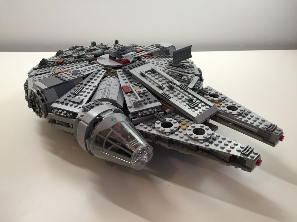
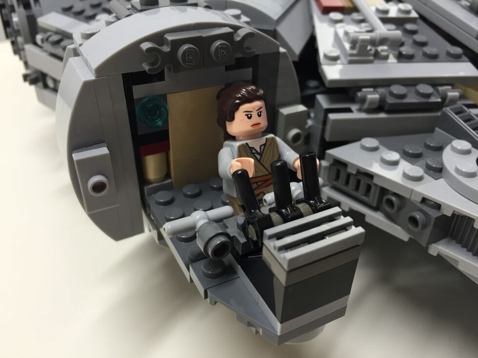
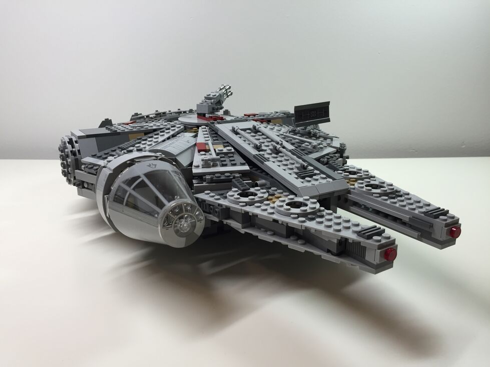
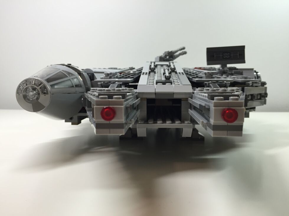
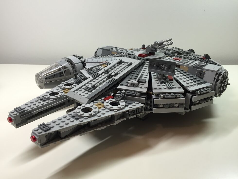
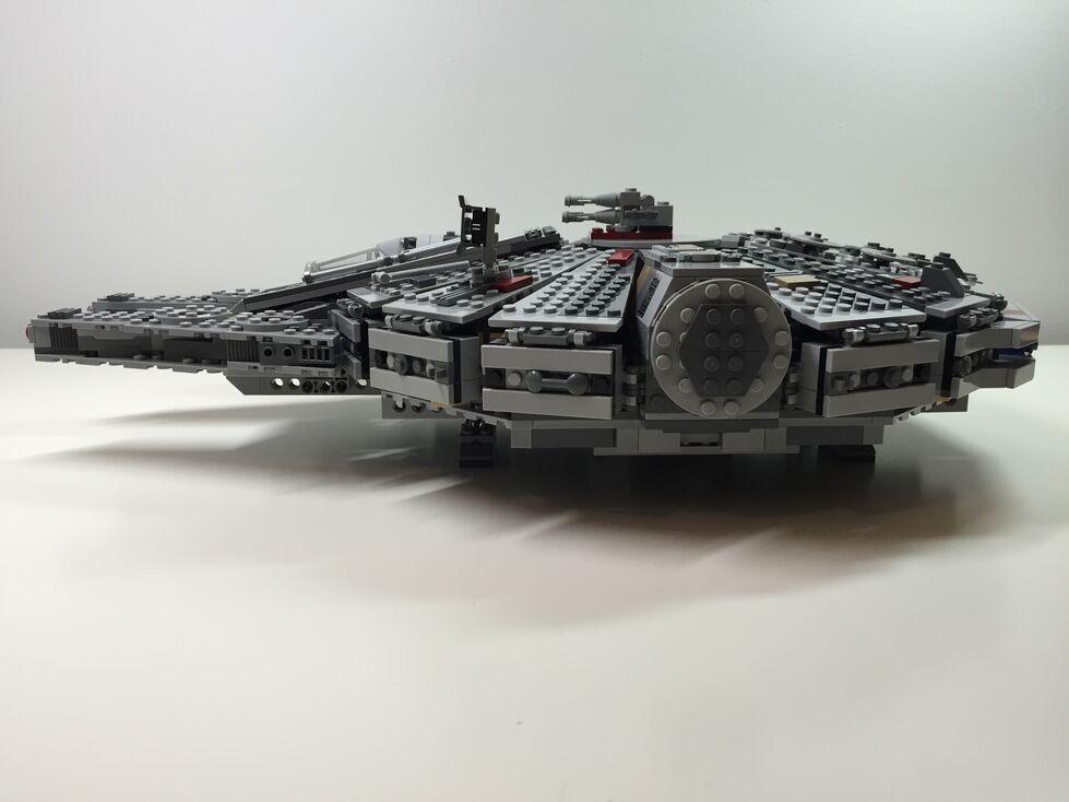
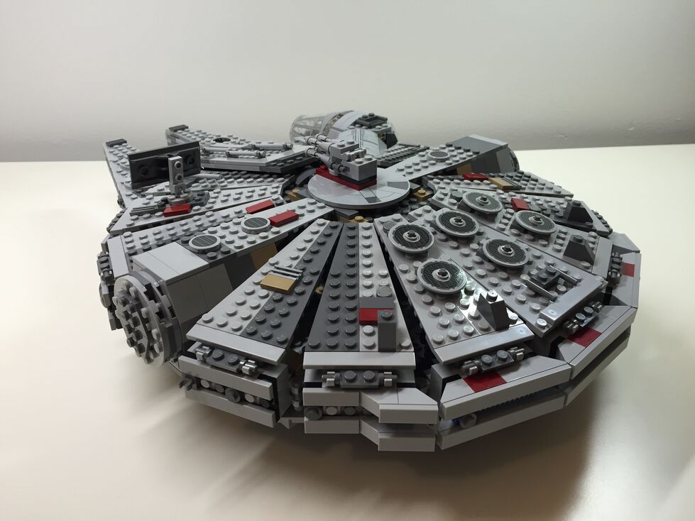
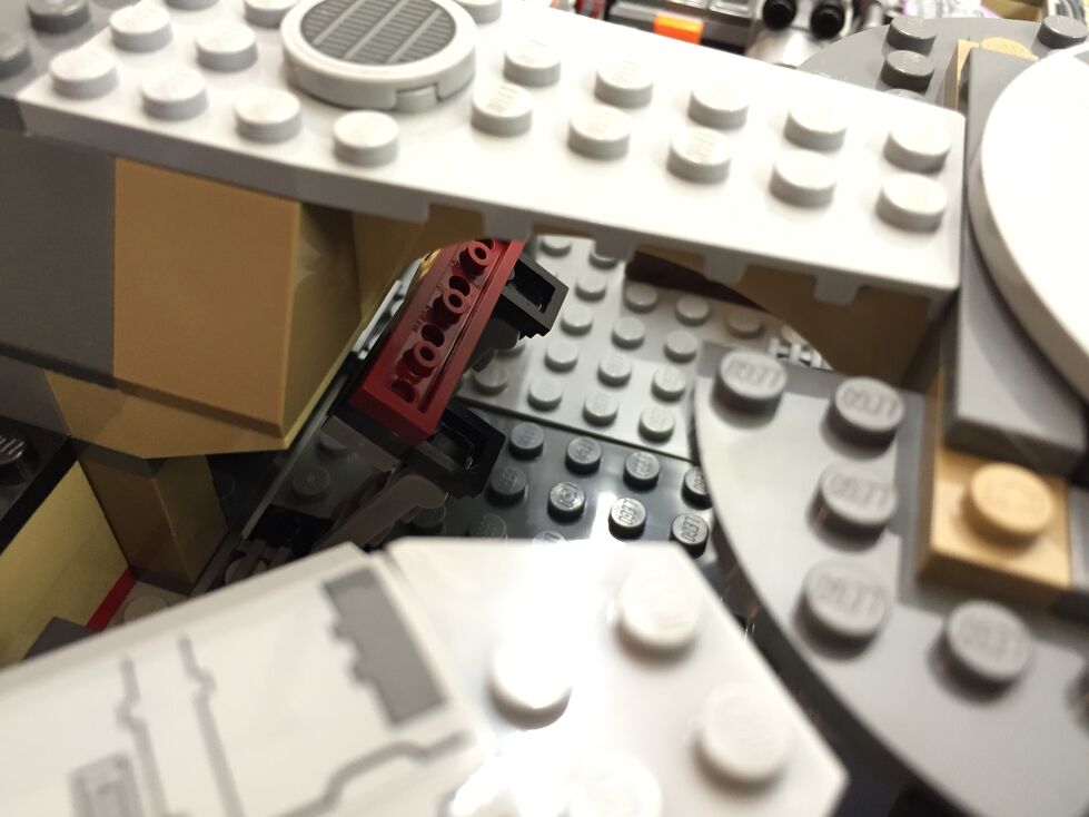
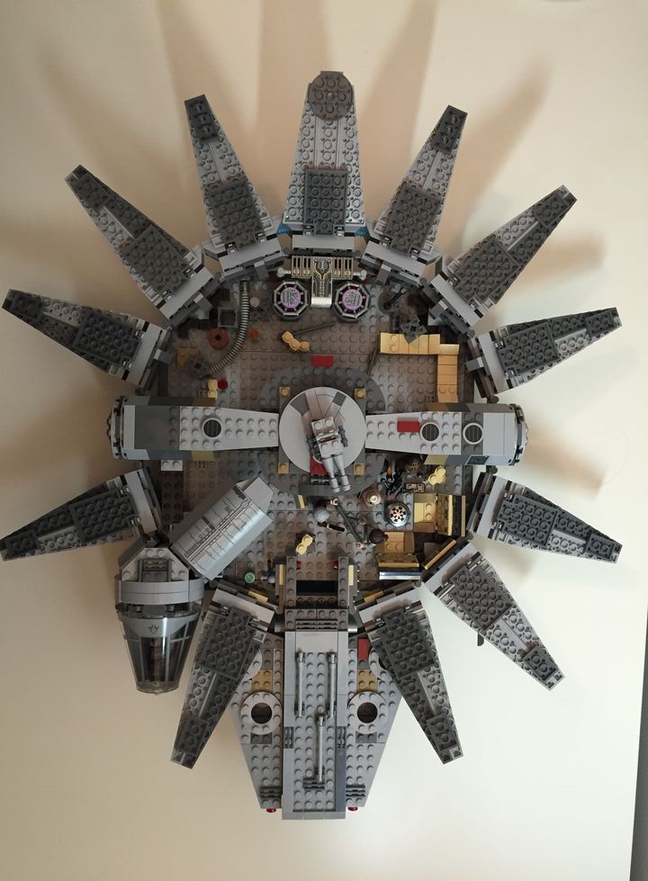
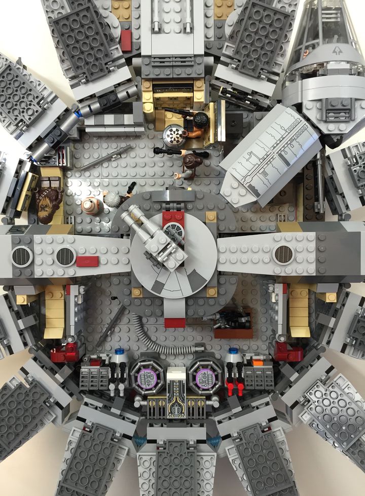
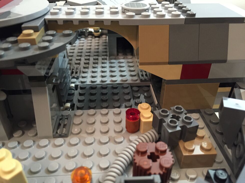
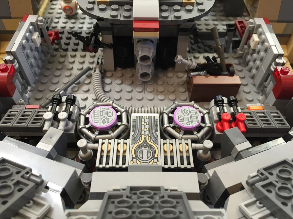
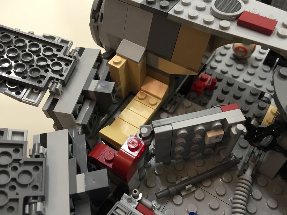
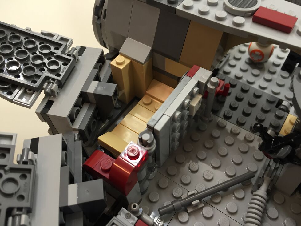
After watching Star Wars Episode VII The Force Awakens for the first of four times (so far), I purchased the new LEGO Millennium Falcon 75105 (LEGO website page and Brickset model page). It is a wonderfully designed model that balances play with detail. This latest Falcon model from LEGO captures how the passage of time and change of hands has affected this storied ship’s appearance in the film. Despite the interior and exterior greebling, the layout of the Falcon is spacious and accommodating for customization by the LEGO builder. It was my intention to customize the Falcon to be more screen accurate in the main hold and cockpit, and more detailed in the engine compartment and rear storage/bunk spaces. Through the process of customization, I worked on the exterior dorsal and ventral sides (including an improvement to the boarding platform. Below, I offer some explanation and photos for each before and after stage of my customization, including the cockpit, exterior dorsal, exterior ventral, interior fore, and interior aft.
Cockpit, Before Customization
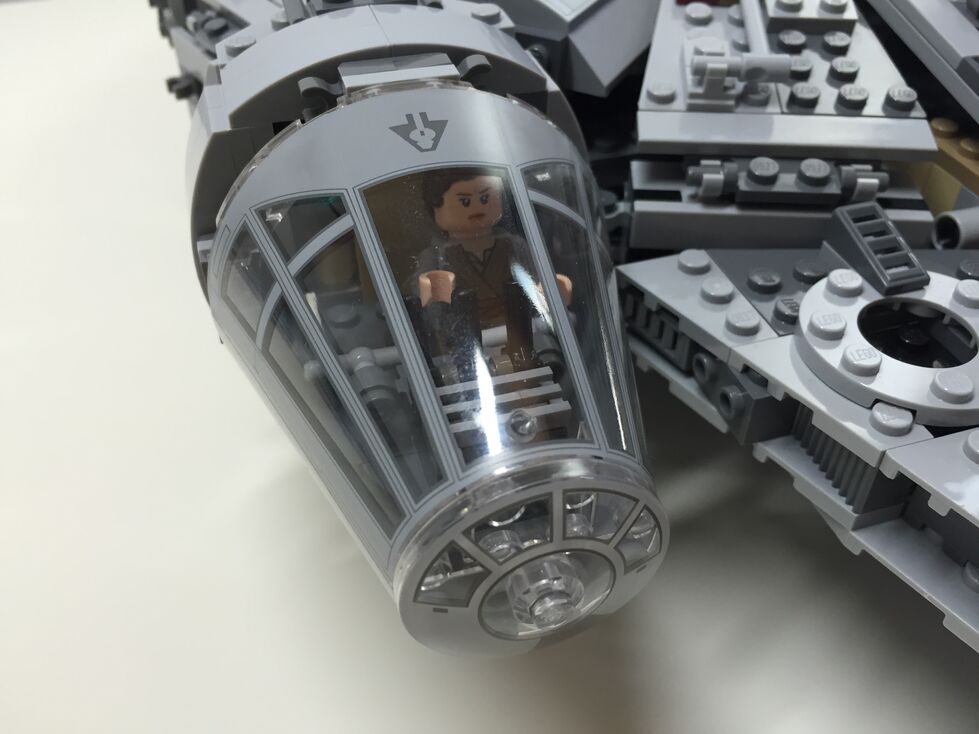
The original cockpit accommodates two minifigures–one sitting forward on the right (pilot) and one sitting one row behind on the left (copilot). It comes with a single lever for control and a printed wedge brick with cockpit controls. Due to the conical elements used for the cockpit, space is extremely limited. However, the rear of the cockpit has a strange design that is not evocative of the rear of the cockpit, which would have controls, lights, and a door. I targeted these issues in my customization seen below.
Cockpit, After Customization
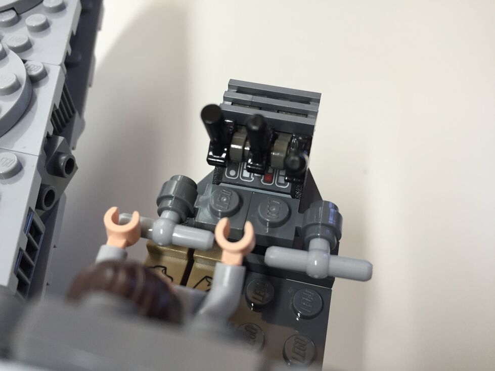
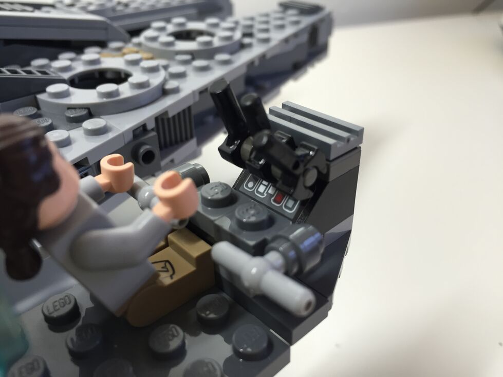
In my customization of the cockpit interior, I raised the control panel by one plate and gave the pilot and co-pilot handle-bar controls like in the films. Above the directional control bars, there are three adjustable levels sitting on top of the printed control panel wedge brick for controlling the engines.
Exterior Dorsal, Before Customization
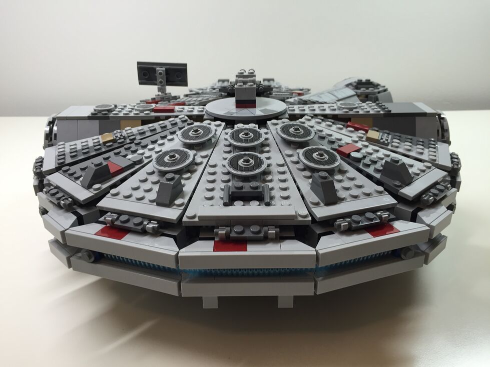
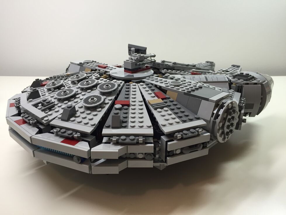
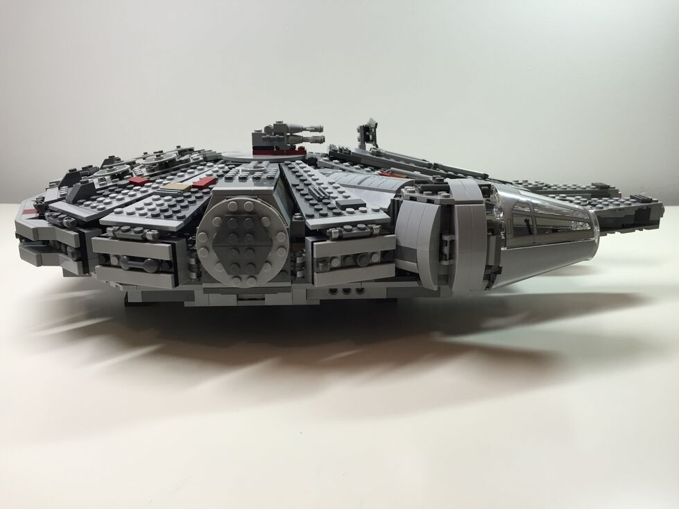
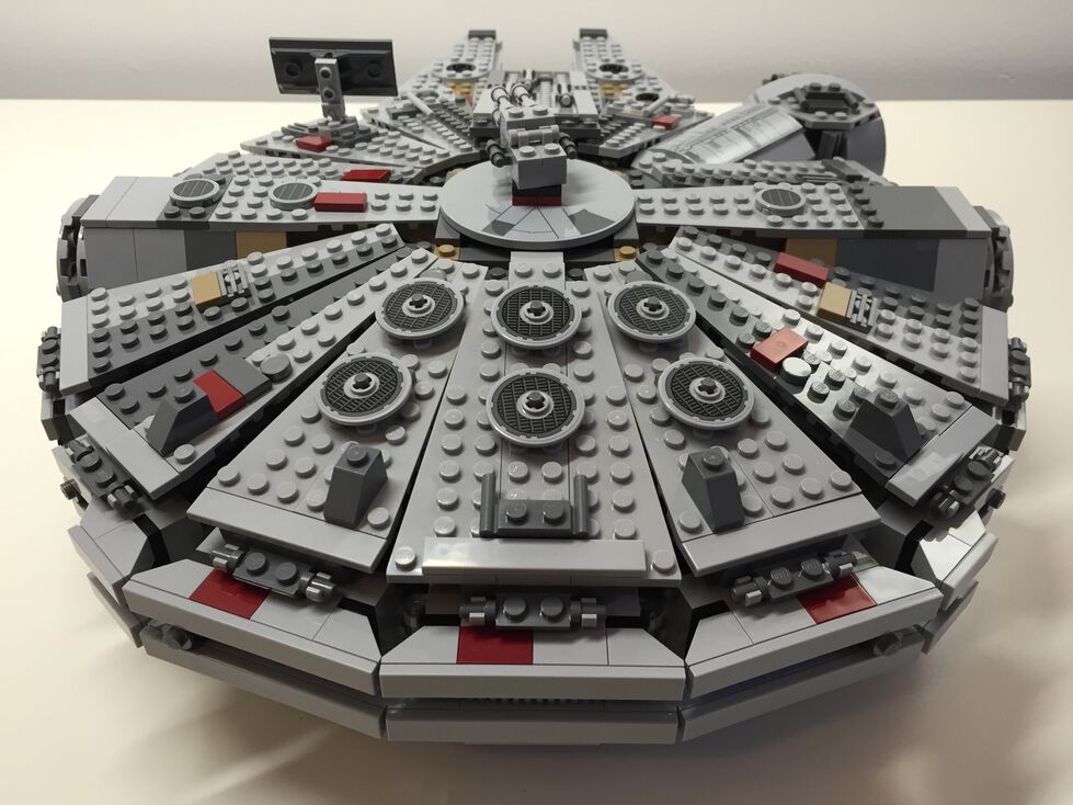
These images are of the Falcon’s exterior before any customization. Of note, the Millennium Falcon’s fore running lights are red instead of clear (a change depicted in The Force Awakens), and a less clean exterior to illustrate its aging and modifications.
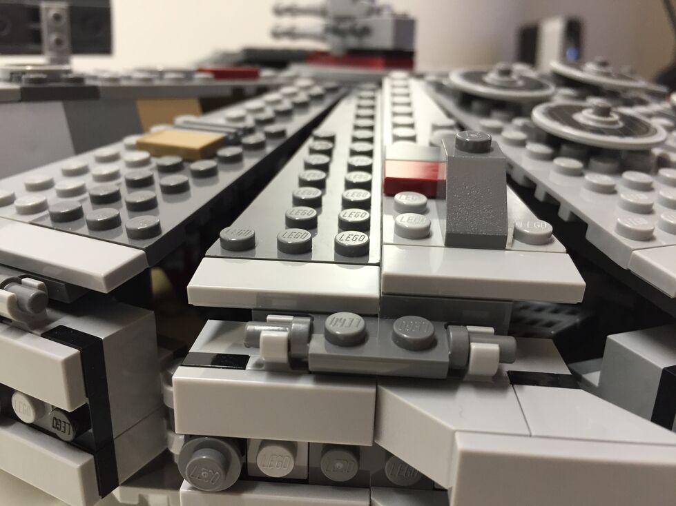
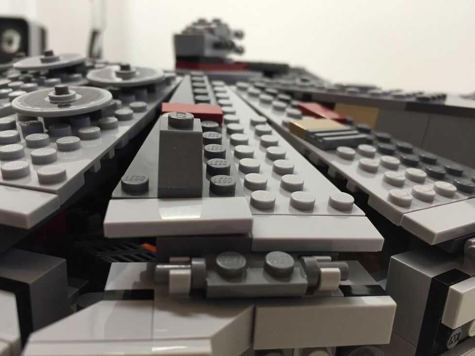
Exterior Dorsal, After Customization
The one external element that I wanted to accentuate as much as possible was the slightly raised panels above the rear quarter over the engines. This was easily accomplished by adding a single plate above the hinge for each sectional panel, and adding a single plate height to half of the bordering panels. The latter, however, also required finding 1×3 flat plates for the segmented panels as seen below.
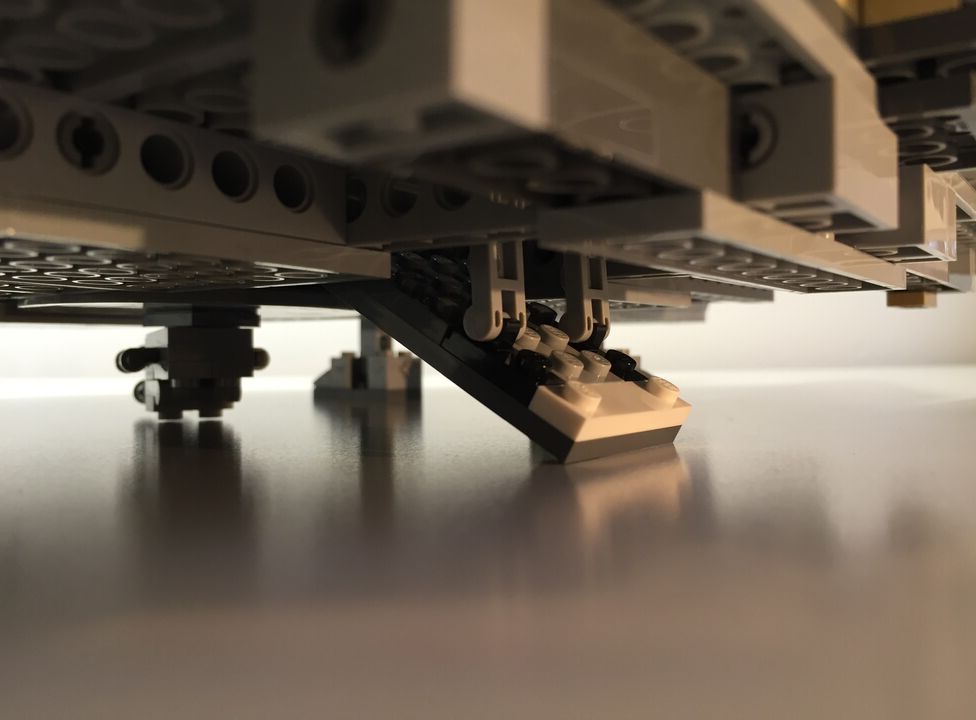
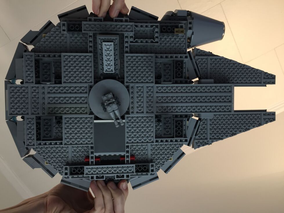
Exterior Ventral, After Customization (no Before photos taken)
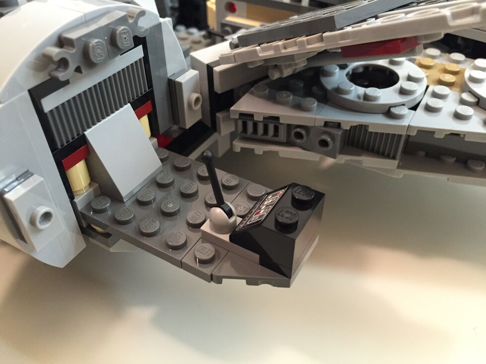
Originally, the boarding platform does not have hydraulic lifters and the bottom of the Falcon is largely exposed to the Technic beams that form the support skeleton for the model. I added the lifters and covered much of the bottom (more can be done when I have the bricks available to accomplish a better approximation of the Falcon’s bottom exterior (angled forward pods and rear hold pod beneath the engines).
Interior Fore, Before Customization
The 75105 Millennium Falcon model continues the innovative “petal” design forming the dorsal fuselage of the spacecraft, which first appeared in the 4504 set and was improved in the 7965 set. The best change from the earlier designs is for the forward bisecting panel leading from the mandibles to the gun turret. Instead of opening up toward the turret (4504) or opening forward toward the mandibles (7965), the panel now swings forward and down between the mandibles thus giving easier access to the builder for play inside the Falcon. The navigational computer is more accurately captured with a sticker applied to a flat plate than printed wedge bricks in 7965, and the Dejarik table is printed on a round shield element. My complaints with the interior design have to do with the inaccuracy of the placement of the Dejarik table/benches and bunks. I focused on this in my customization.
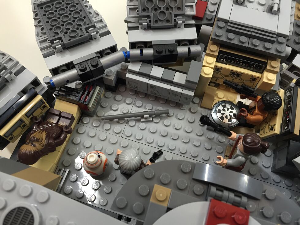
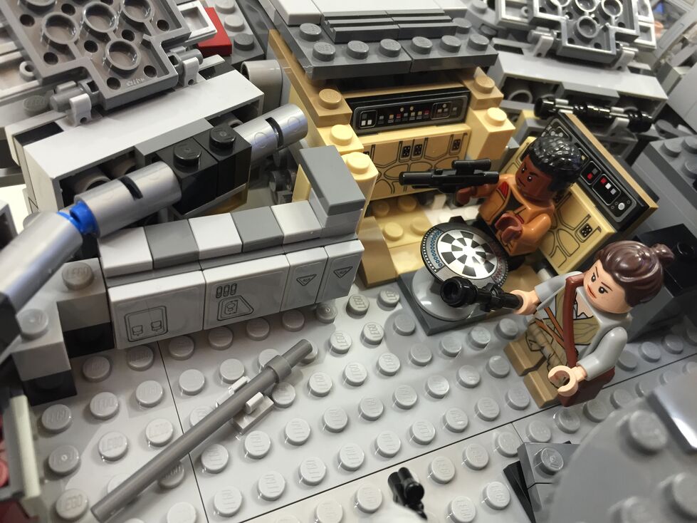
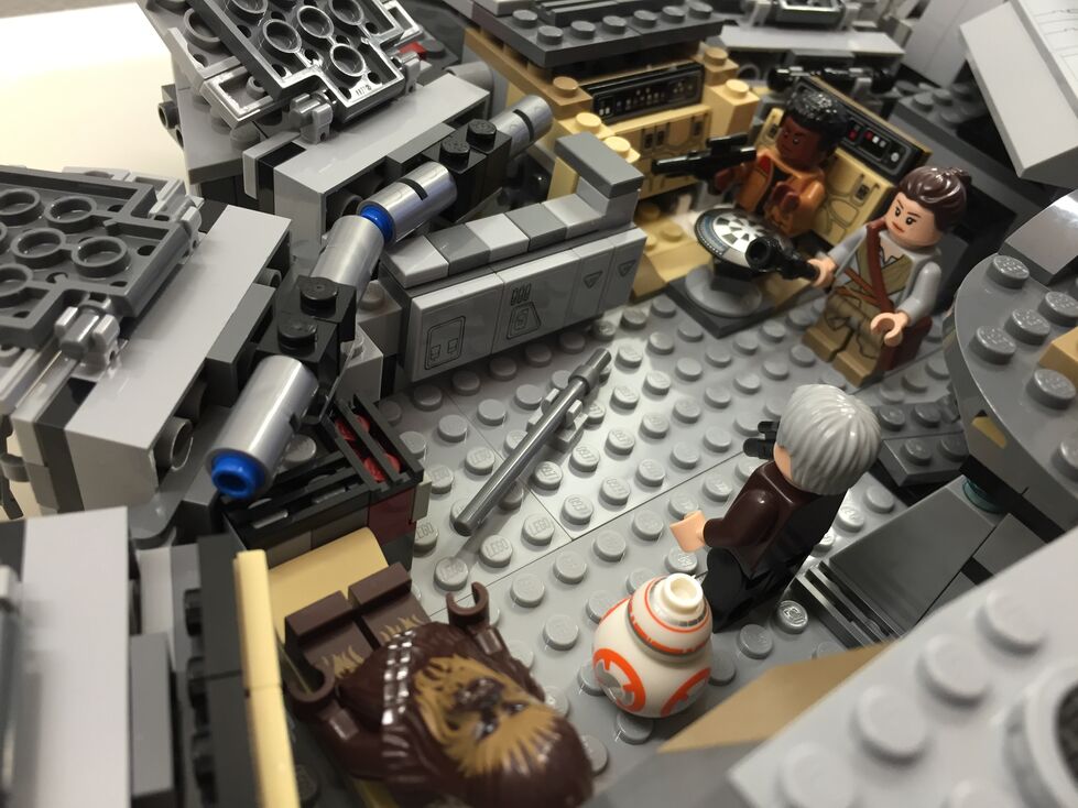
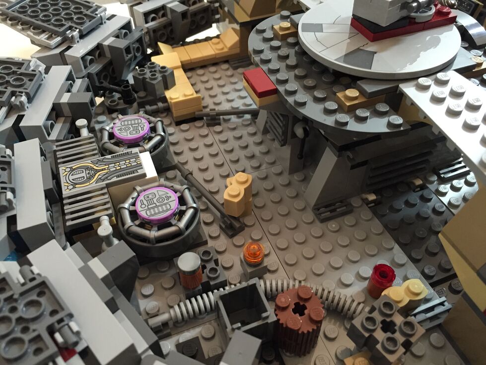
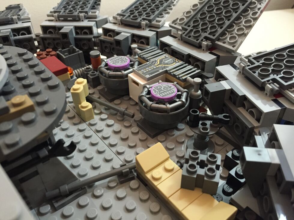
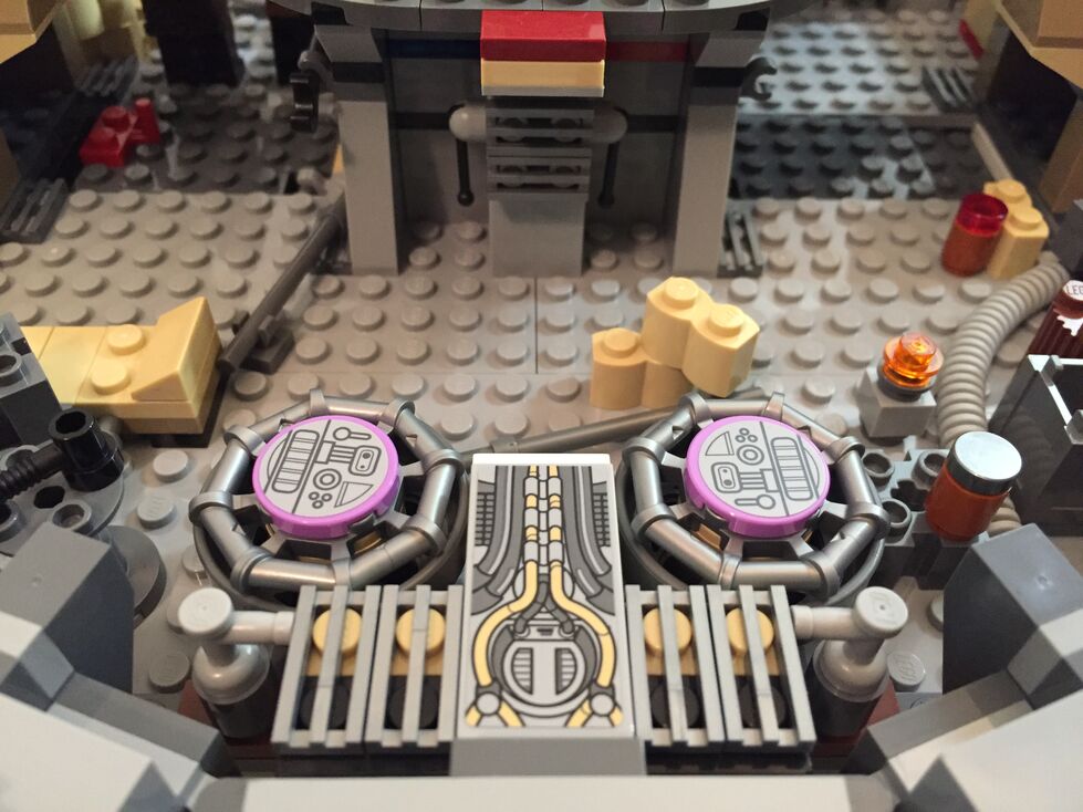
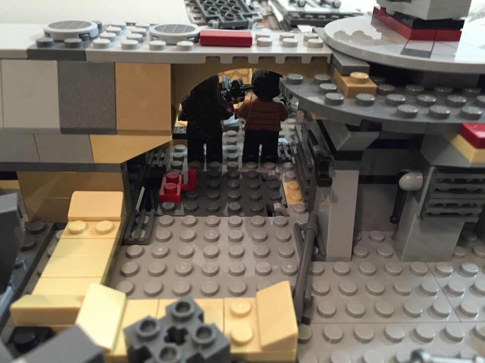
Interior Fore, After Customization
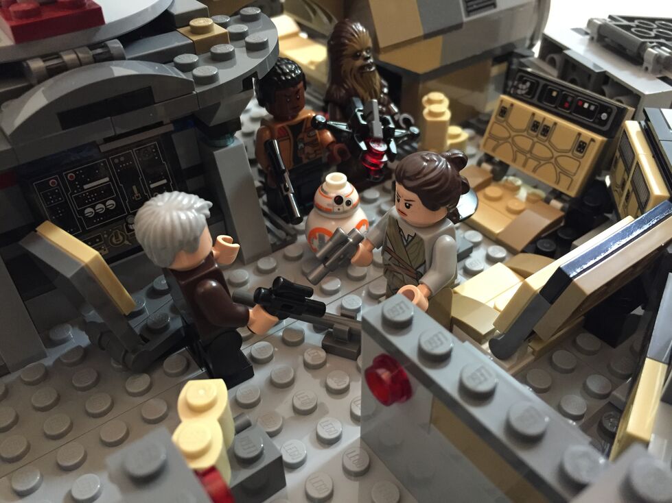
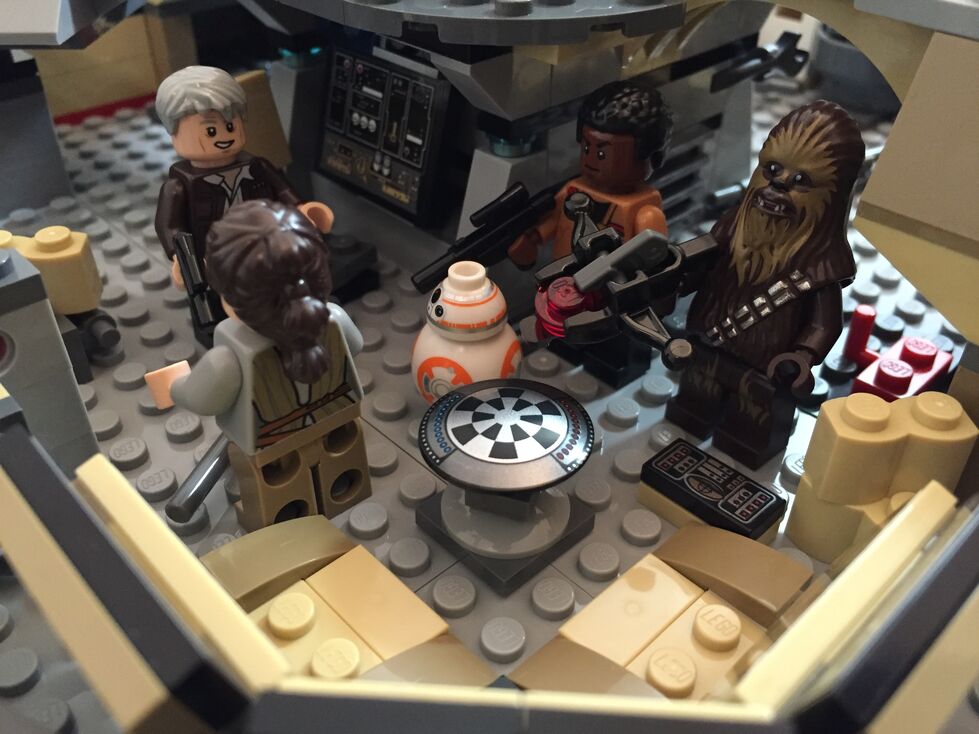
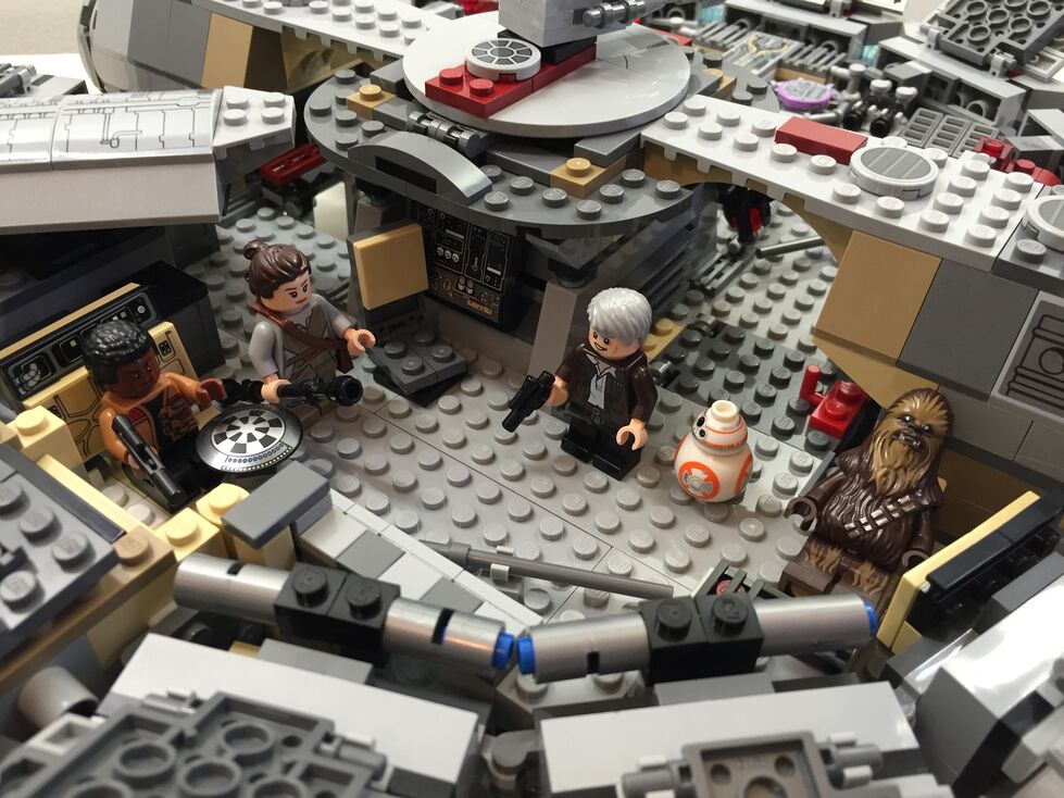
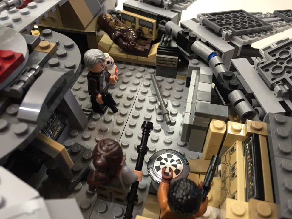
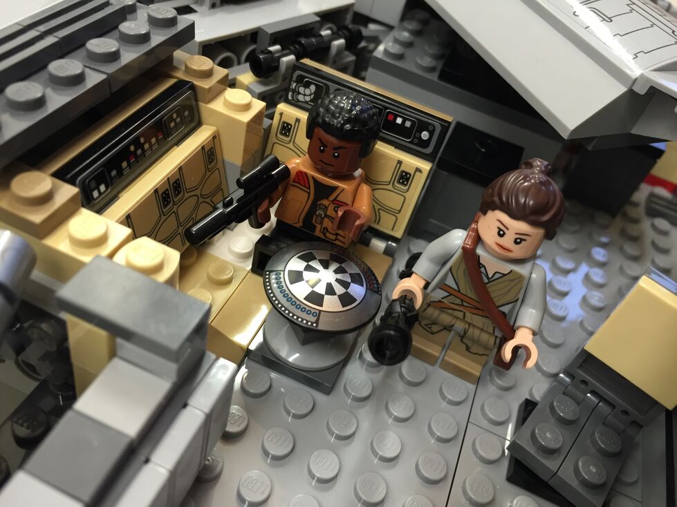
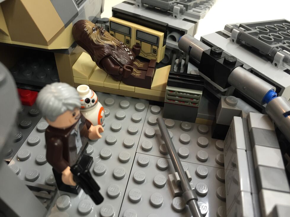
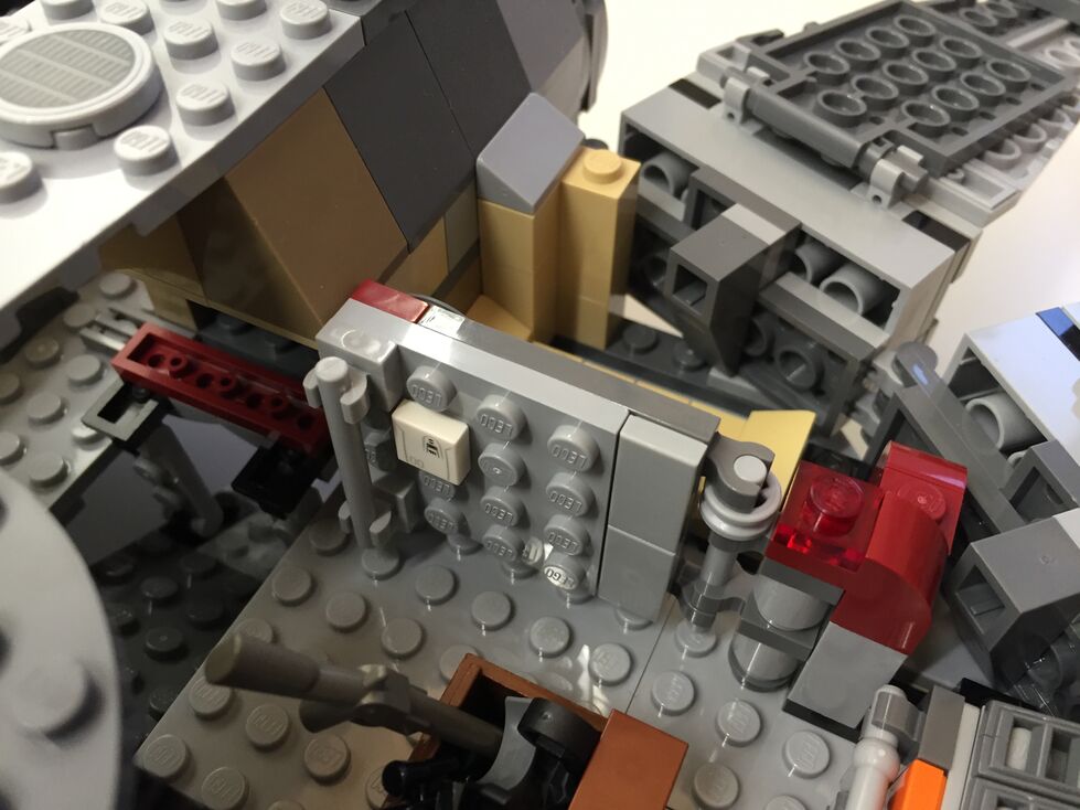
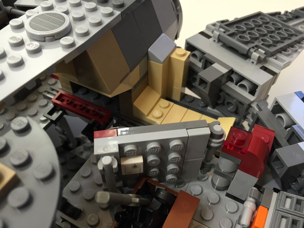
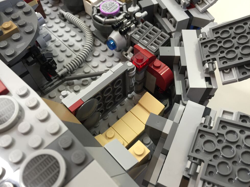
In my customization, I moved the Dejarik table and benches across from the navigation computer, which required rebuilding part of the mandible supports and the swing components for the center panel (to clear the center bench back). I relocated one of the bunks to the end of the hold to create the medibay where Finn bandages Chewbacca’s arm. In the main hold, I constructed a forward wall with panel details taken from the First Order Snowspeeder 75100 set.
Interior Aft, Before Customization
The engine compartment in the rear of the model is similar to the one in 7965. This part of the Falcon captures the junked essence of the Falcon in general and the effects of the passage of time and unkind handling of the Falcon depicted in The Force Awakens. I wanted to keep its garbage appearance while giving the engine compartment greater substantiality.
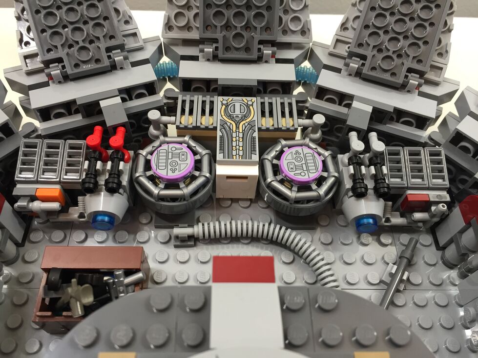
Interior Aft, After Customization
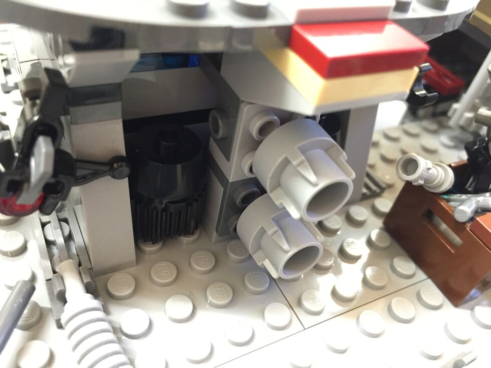
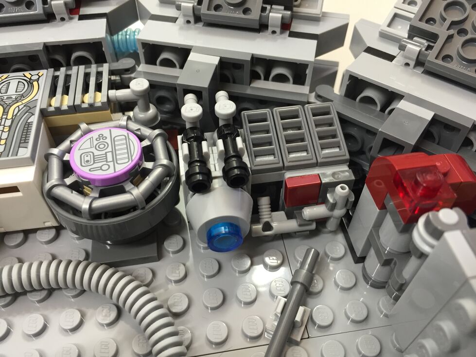
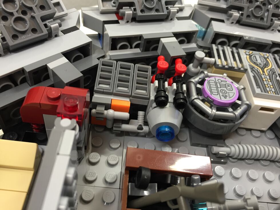
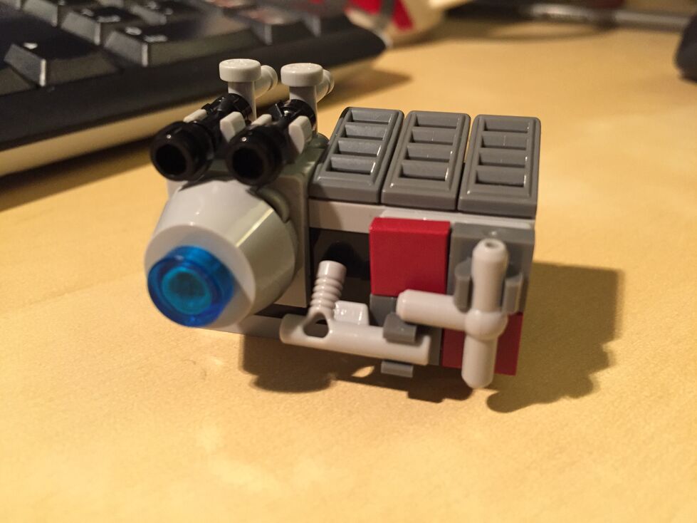
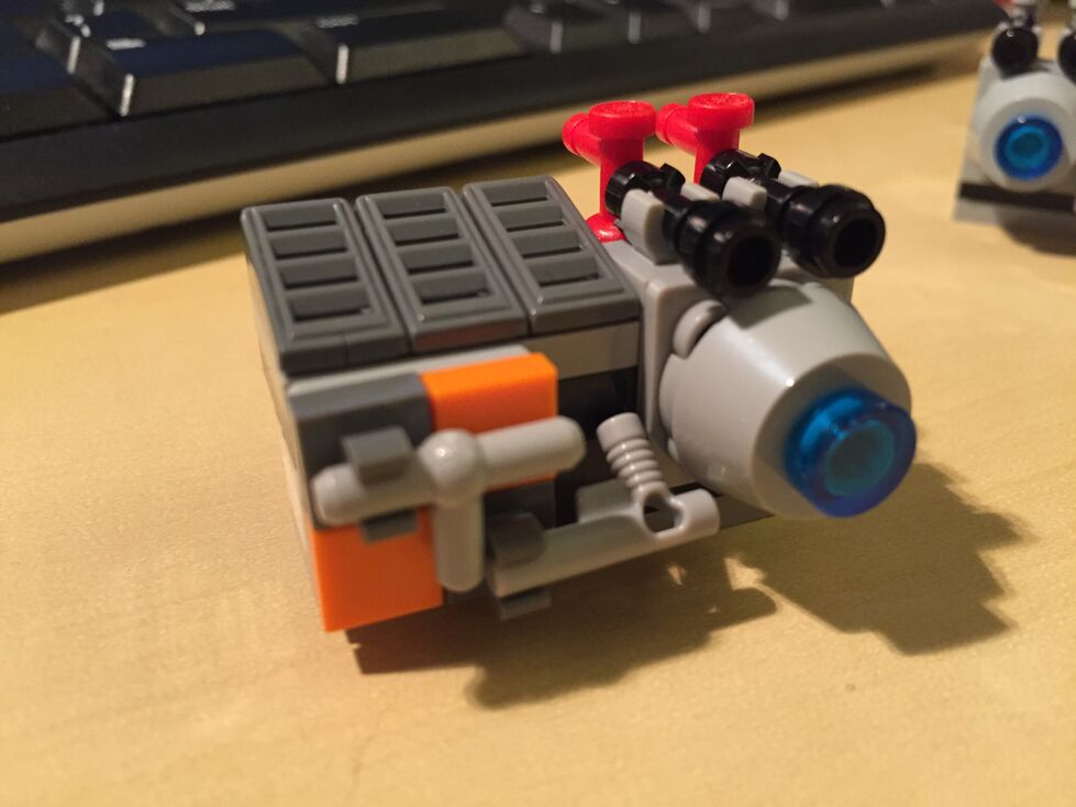
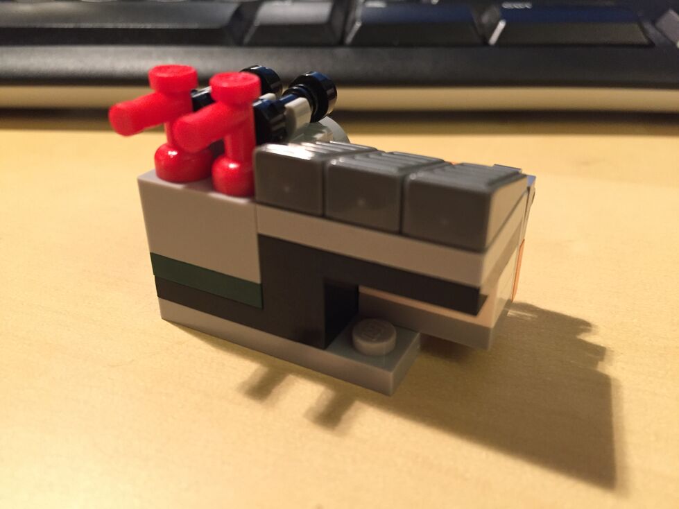
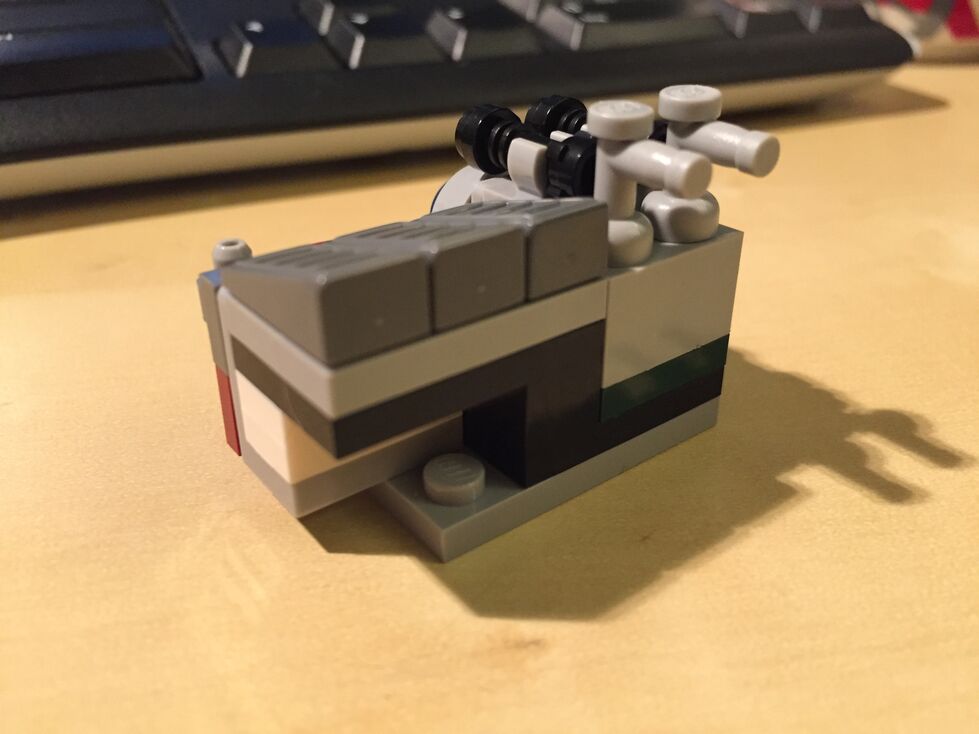
In the rear hold/engine compartment, I constructed two storage rooms/bunks with swinging doors (I would have preferred to have sliding doors but I don’t have the elements to do this while conserving the limited space available), and I designed additional mirrored engine modules that go on either end of the original engine included with the set, which I hope makes the engine look more substantial for a spacecraft capable of completing the Kessel Run in 14, er, 12 parsecs!
Conclusion
I hope to further customize the 75105 Millennium Falcon. As I acquire new bricks and elements, I would like to think about how to better integrate the engines into the design and aesthetic of the YT transport. Other goals include, integrate a mechanism for lowering and raising the boarding platform, similar to the 4504 set, design screen accurate landing gear that raise the Falcon by at least one plate higher while on display, and further integrate my customization into the model so that it attains a unity of design instead of a piecemeal added-on quality.
If you have customized the 75105 or other Millennium Falcon sets, please sound off in the comments. Thanks for stopping by!
My Cardboard Box Raspberry Pi 2, Model B with 7″ Touchscreen Display and wireless keyboard.
This guide demonstrates how to install Raspbian on a Raspberry Pi 2, Model B, connect the Raspberry Pi to a 7″ Touchscreen LCD, and integrate the computer and touchscreen in a cardboard box (which doubles as a case and storage for battery, keyboard, and cables).
I got interested in the Raspberry Pi, because it has many capabilities for learning: kitting out a computer, installing a Linux-based operating system, programming interactive software, and building with electronics. In particular, I am interested in how the Raspberry Pi can be used to create interactive software and be a platform for digital storytelling (which figures into one of the upcoming classes that I will be teaching at City Tech–ENG 3760 Digital Storytelling).
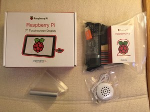
My haul from Tinkersphere.
Instead of buying my kit online, I wanted to shop local to get started. Originally, I considered going to Microcenter, which is near where I live in Brooklyn. Unfortunately, they were sold out of the touchscreen display that I wanted. Instead, Y and I took a train into Manhattan and visited Tinkersphere where one of their helpful staff guided me to the things on my digital grocery list. I purchased Tinkersphere’s pre-made Raspberry Pi 2 kit, a 7″ Touchscreen LCD display, a battery pack (in retrospect, I should have purchased two of these, which I will discuss below), and a mono speaker with 1/8″ plug.
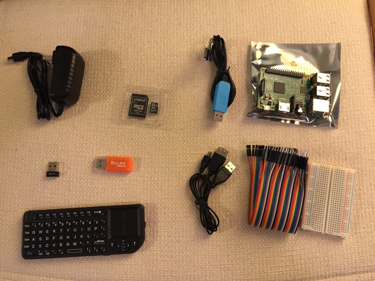
Contents of Tinkersphere’s Raspberry Pi 2, Model B kit.
Tinkersphere’s Raspberry Pi 2, Model B kit includes all of the basic equipment needed to begin working with this tiny computing platform. The kit is built around the Raspberry Pi 2, Model B computer with a 900MHz quad-core ARM Cortex-A7 CPU, 1GB RAM, 4 USB ports, 40 GPIO pins, HDMI port, ethernet port, combined 3.5mm audio jack and composite video, camera interface (CSI), display interface (DSI), micro SD card slot, and a VideoCore IV 3D graphics core. Additionally, the kit includes a wireless keyboard/trackpad, USB wifi adapter, 8GB micro SD card with NOOBS (the easy to use Raspbian installer), USB micro SD card reader, breadboard, wires, and 5v power supply.
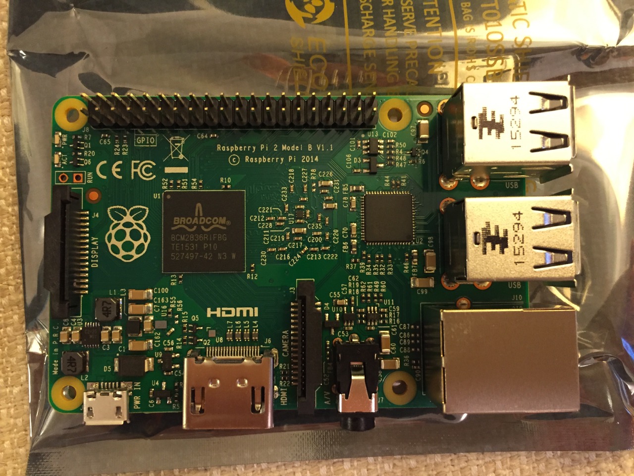
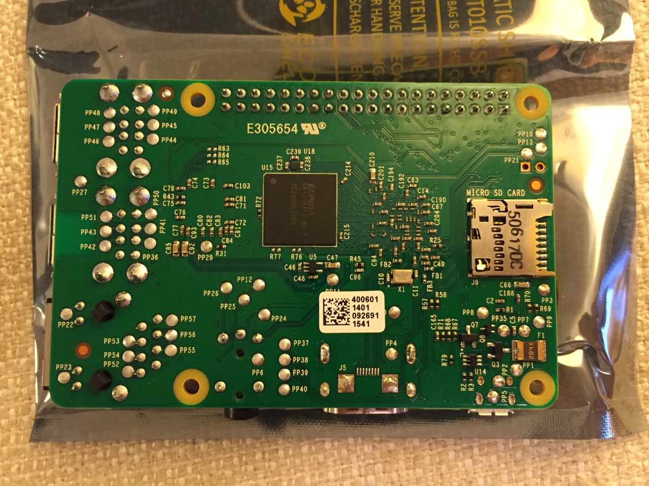
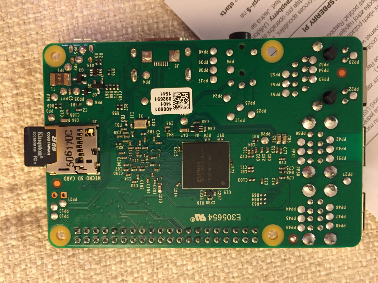
To begin the setup, we should orient ourselves with the Raspberry Pi. This is the Raspberry Pi 2, Model B computer viewed from the top and the bottom:
Raspberry Pi 2, Model B, Top View.
Raspberry Pi 2, Model B, Bottom View.
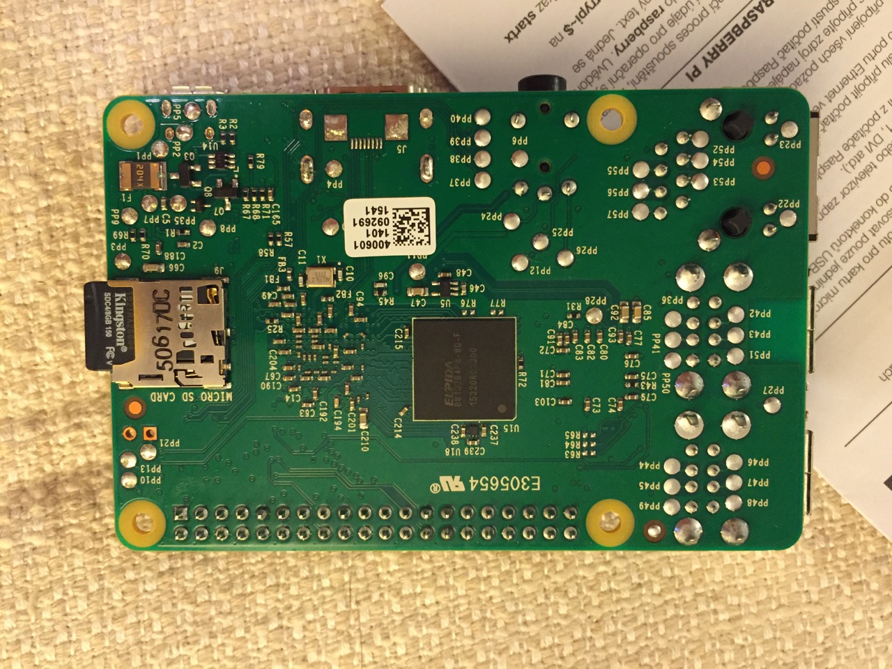
The first thing that we need to do is insert the micro SD card with a copy of NOOBS pre-copied. If you need a copy of NOOBS for your own micro SD card, you can download it from here and follow the instructions here for formatting and copying the files from a Mac or PC to the micro SD card. The Raspberry Pi’s micro SD card slot is located on the bottom side of its circuit board. A micro SD card goes in only one way which allows you to press it in. If correct, the card should “click” and stay as seen in the photos below.
Insert the micro SD card like this.
Press the micro SD card in and it will stay in place with a “click.”
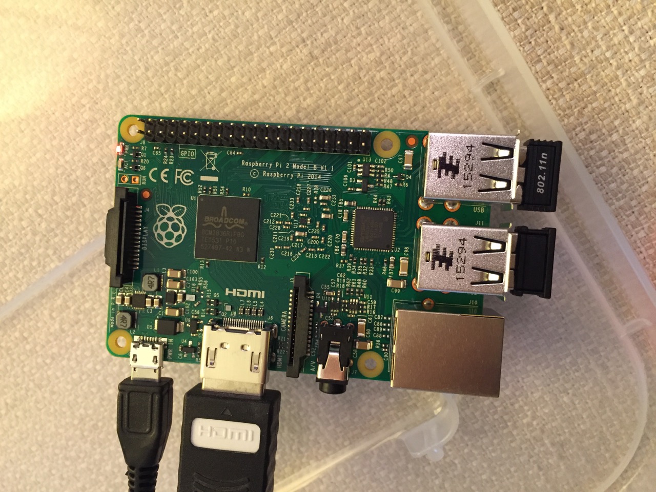
The Raspberry Pi connected from left to right: micro USB power input from 5v power supply, HDMI, wireless keyboard/trackpad receiver, and wifi adapter.
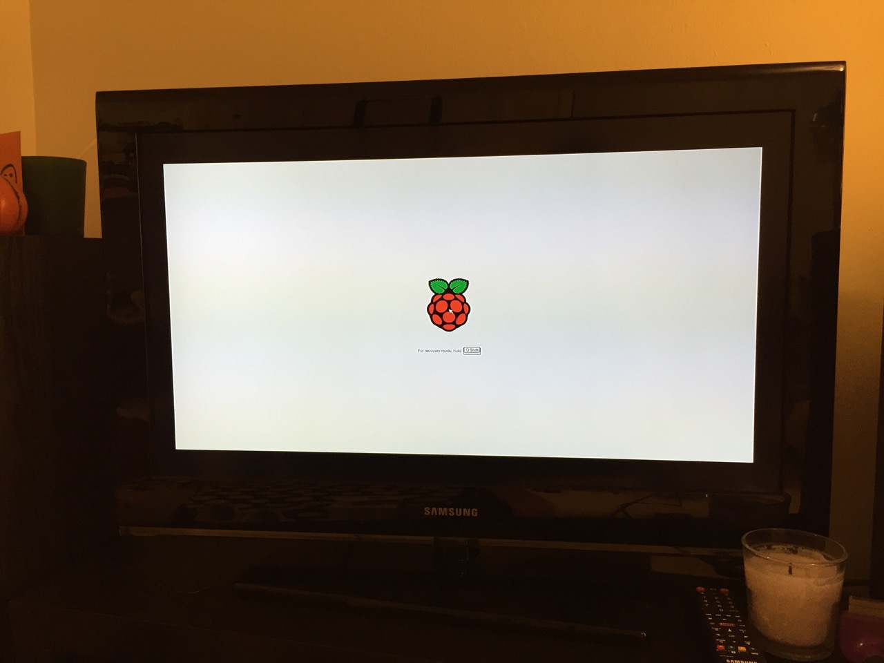
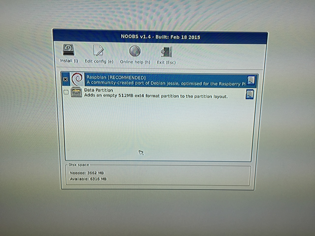
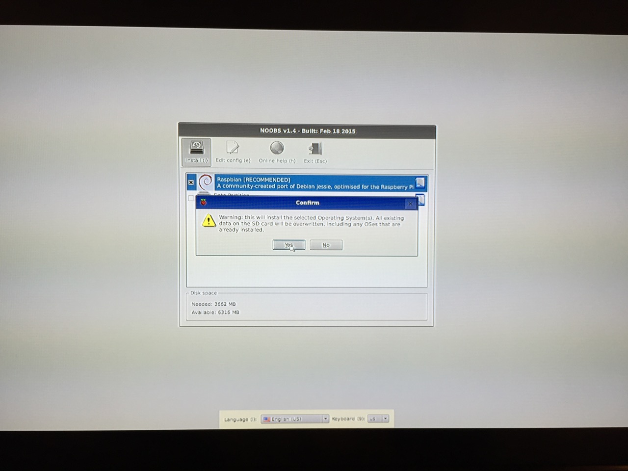
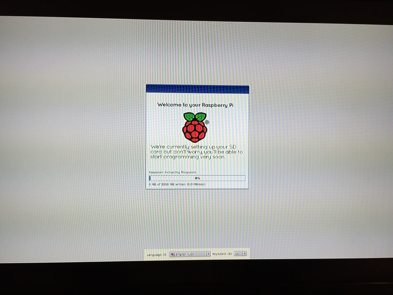
Next, connect the Raspberry Pi to a display (such as a TV) with HDMI, and plug in the wifi adapter and wireless keyboard into two available USB ports. Alternatively, you can connect the Raspberry Pi to the Internet via ethernet and to a wired keyboard and mouse. Then, connect it to the 5v power supply. As soon as it is plugged in, the Raspberry Pi is turned on and operational. It will begin to boot from the micro SD card’s NOOBS installer, which will guide you through the process of installing Raspbian. See the images below to see what this looks like and what choices you should make for a basic installation.
NB: While we could have connected the 7″ Touchscreen Display to the Raspberry Pi before beginning the installation, the current version of NOOBS would not detect and use the touchscreen display. It is necessary for Raspbian to be installed and updated before the 7″ Touchscreen Display will be recognized and used as the Raspberry Pi 2’s primary display.
NOOBS boot screen with the Raspberry Pi logo.
The NOOBS installer asks what you would like installed. Place a check next to Raspbian.
The NOOBS installer will ask that you confirm your choice. If you haven’t already done so, choose US keyboard and locationalization at the bottom of the screen before proceeding. Then, confirm.
The installation will proceed and complete. With the micro SD card that I have and without overclocking the Raspberry Pi, it took about 20-30 minutes for the installation to complete.
After rebooting following the installation, the raspi-config tool launches. This program gives the user easy access to many configuration options for the Raspberry Pi including how it should boot (automatically login and load xwindows, or boot to a command prompt login), and if you would like to overclock the Raspberry Pi for additional performance (use this option with caution–you will likely want to add heat sinks and increased ventilation if you overclock the system). I configured my Raspberry Pi to operate at normal speed and to boot to the command line with login.
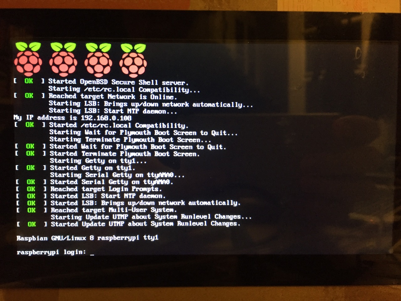
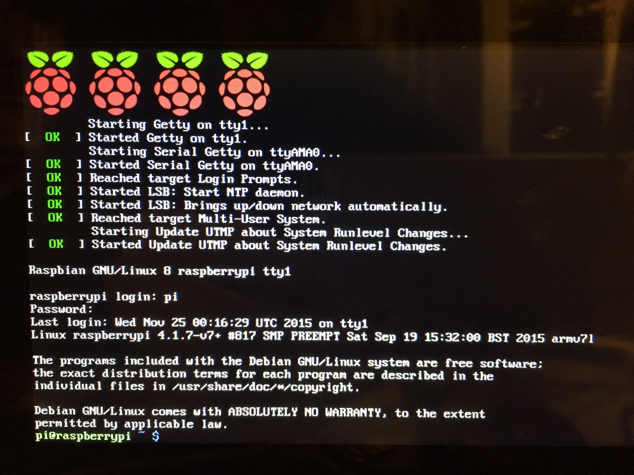
After booting into Raspbian, the first thing that you see is the login prompt.
The default login for the Raspberry Pi is username “pi” and password “raspberry”. Type each of these credentials in when asked followed by pressing the Enter key. Then, you will find yourself at the command line interface (CLI).
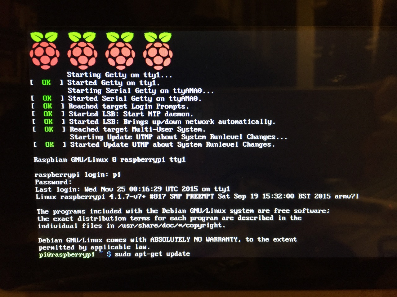
Before setting up the 7″ Touchscreen Display, we need to update Raspbian. To do this, first type: “sudo apt-get update”. If prompted to install anything because it will take a certain amount of space, simply type “y” and press “Enter”.
Entering a command at the prompt in Raspbian’s CLI.
To explain what this command means, “sudo” runs a command as superuser, or the user that is all powerful on a linux system. The command that you want to run as superuser is “apt-get,” which is a package manager, or a manager of software packages that run on your Raspberry Pi. “update” is a modifier for “apt-get,” and its purpose is to tell “apt-get” to update its index of available software packages with what is stored on the remote software repository (where your Raspberry Pi is downloading its software from).
After the update operation completes and you return to the command prompt, type: “sudo apt-get upgrade”. Similarly, agree to the prompts with “y” and “Enter”. The “upgrade” modifier to “apt-get” tells it to upgrade the software based on what it learned when updating its index with the previous command. Thus, when you run these two commands, you should run the update command first (learn) and the upgrade command second (act on what was learned).
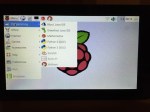
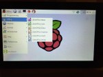
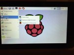
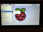
To launch into Raspbian’s X11, type “startx”. Inside X11 or xwindows, you will find many of the GUI-based software that really makes the Raspberry Pi sing: Scratch, Python, Mathematica, and more. If you have never used X11, it works a lot like Windows 95/98 except that the Start Menu bar is at the top of the screen instead of at the bottom and “Start” is replaced by “Menu.” Some quick launch apps are directly available to be launched with a single click from the start bar (such as Terminal, the Epiphany web browser, and Wolfram Mathematica) while all of the installed X11 programs are available from the “Menu.” Below are images of the Raspbian desktop and navigating through some of the default programs available.
To easily install additional software, you can install the Synaptic Package Manager, which simplifies finding and installing software packages by wrapping package management in an easy-to-use GUI. From inside X11, open Terminal and type “sudo apt-get install synaptic”. This will install Synaptic, which you can open by clicking on Menu > Preferences > Synaptic Package Manager (more info on this and other Raspberry Pi stuff on Neil Black’s website).
When you done browsing around, you can click on the and choose to shut down. After a few moments, your display should show a blank screen and the activity lights on the back of the Raspberry Pi (red and green) should only be showing a solid red. At that point, unplug the micro USB 5v power adapter. If you are ready to install the 7″ Touchscreen Display, unplug the HDMI cable, too.
In the images below, I demonstrate how to assemble the 7″ Touchscreen Display and connect it to the Raspberry Pi. I followed the excellent instructions available on the official Raspberry Pi website, which also details how to install the Matchbox virtual keyboard for using the touchscreen without a keyboard.
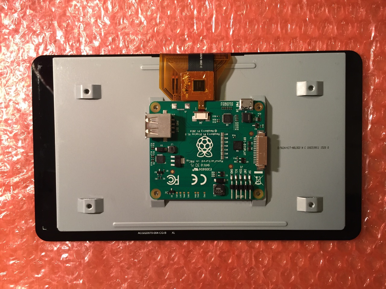
To begin connecting the 7″ Touchscreen Display to the Raspberry Pi, place the screen facing down.
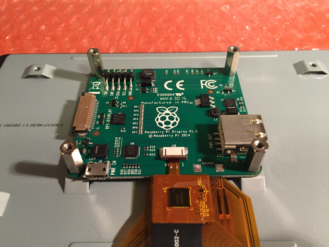
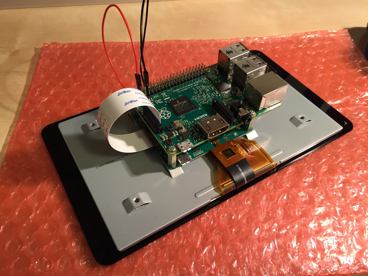
Screw in the standoff posts to hold the display controller card to the display. Connect the display and touchscreen wires as described on the official installation guide.
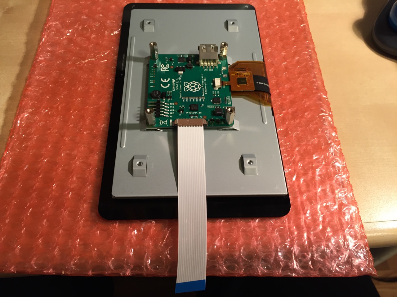
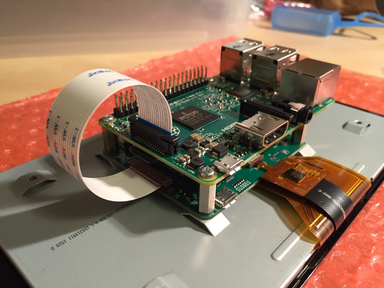
Insert the display cable to the video input on the controller card.
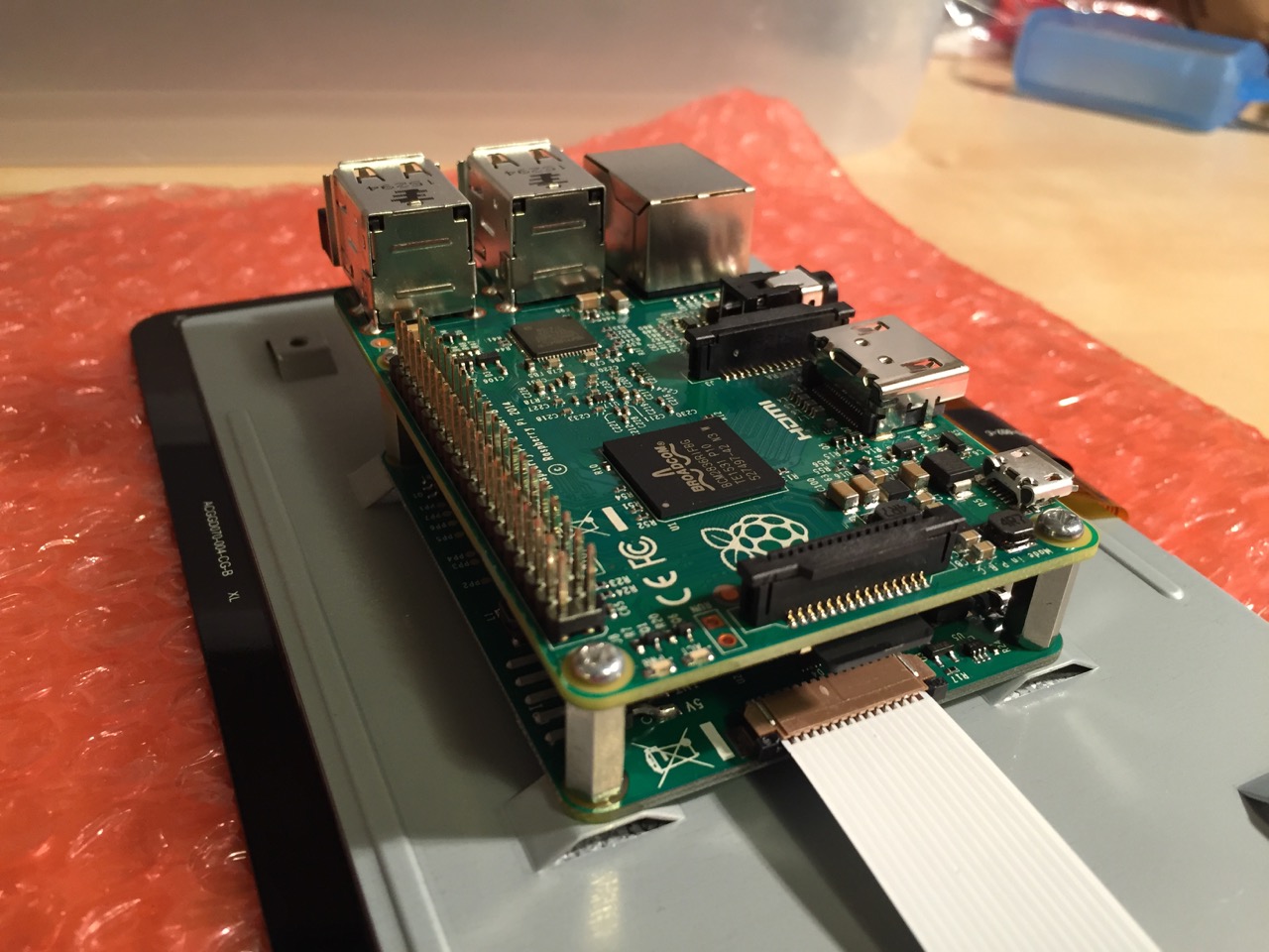
Place the Raspberry Pi above the display controller card and attach with the supplied screws that screw into the top of the standoff posts.
Connect the other end of the display cable into the output connector on the Raspberry Pi.
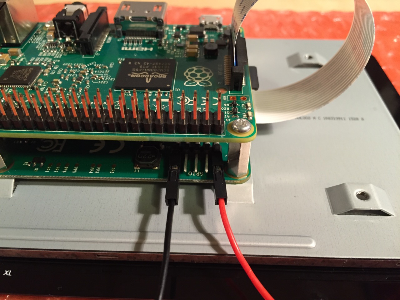
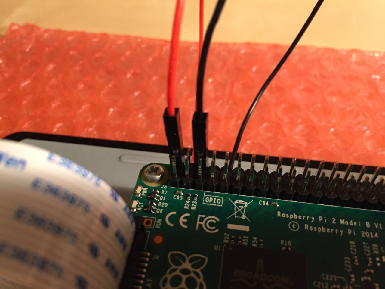
Use the supplied jumper wires to connect connect the power input of the display controller card…
…to the power output leads on the GPIO pins on the Raspberry Pi. This is one of three possible powering configurations–the other two involve USB.
This is the rear of the 7″ Touchscreen Display assembled with the controller card and Raspberry Pi.
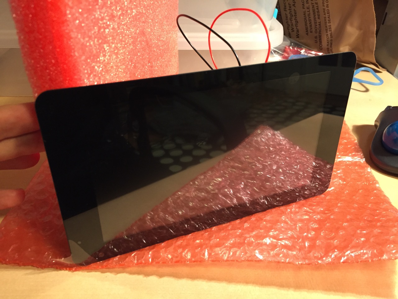
This is the front of the 7″ Touchscreen Display with the power leads sticking out from behind.
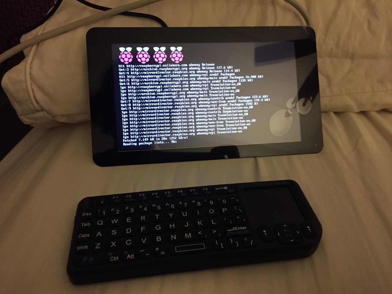
This is the Raspberry Pi powered up again with the 7″ Touchscreen Display.
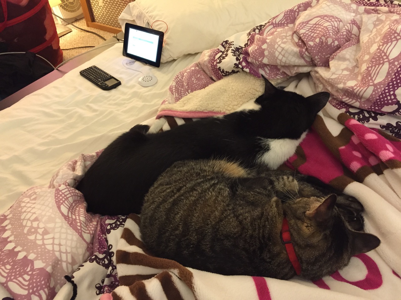
Mose and Miao had lost interest in the project by this point.
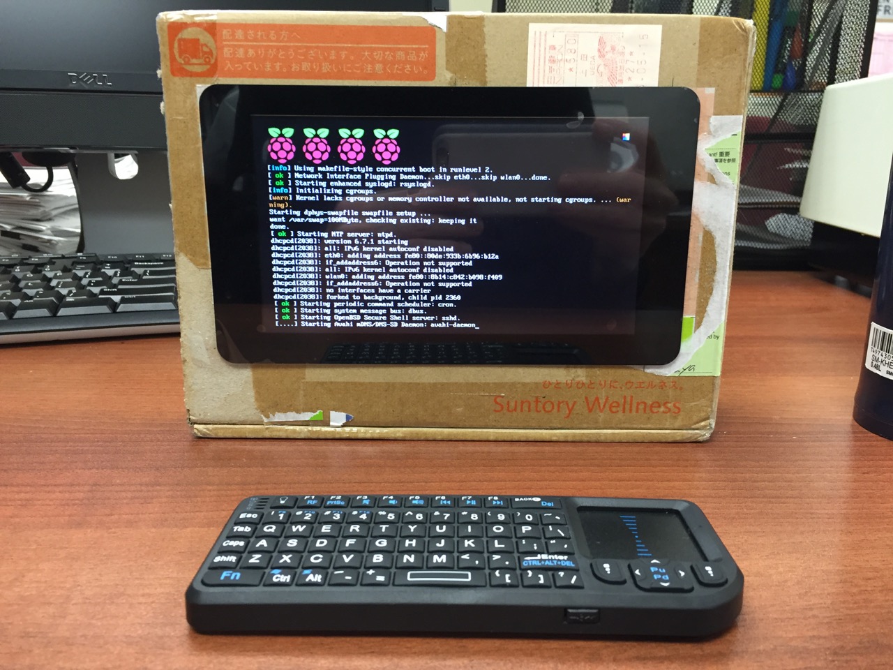
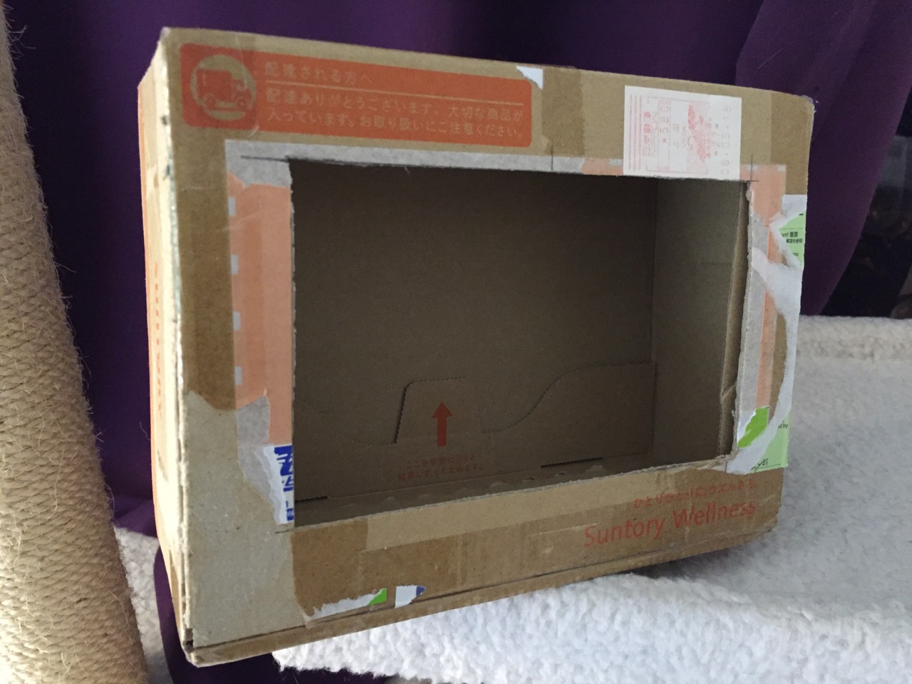
To complete the project, I cut a hole into a Suntory shipping box from Japan that is the exact same size as the 7″ Touchscreen Display box, which would work well, too. It is works well for holding up the Raspberry Pi and storing its accessories when I go between home and work.
Of course, you can use the Raspberry Pi with or without a case depending on your needs. I used the Suntory cardboard box from Japan for practical reasons (thinking: William Gibson: “the street finds its own use for things”–it’s a good size, on-hand, and looks cool) and research reasons (thinking about my work on proto-cyberpunk and the hidden nature of computing, which is an idea explored in my previous blog post about the poster that I created for the 13th annual City Tech Poster Session).
I have run the computer and touchscreen from the 5v battery that I purchased from Tinkersphere, but I get a graphics warning that the Raspberry Pi is under voltage (a rainbow pattern square persists in the upper right corner of the display whether in the CLI or xwindows). I might get a second battery to run the display alone, which would help me troubleshoot if the battery that I have now is actually outputting enough voltage and amperage needed by the Raspberry Pi alone. In the meantime, I am running everything at my desk with the 5v power adapter, which provides ample power for the Raspberry Pi and 7″ Touchscreen Display.
In the future, I would like to use the Raspberry Pi in a writing or technical communication course. There are many ways to leverage the technology: problem solving, writing about process, creating technical documents such as reports and instructions, using the Raspberry Pi as a writing/multimodal composing platform, digital storytelling with tools that come with the Raspberry Pi, and more. These ideas are built only around the Raspberry Pi and its software. A whole other universe of possibilities opens up when you begin building circuits and integrating the Raspberry Pi into a larger project.
The basic cost of entry with the platform is $30 for the Raspberry Pi 2, Model B and a few dollars for an 8GB micro SD card. If you have access to a display with HDMI, a USB keyboard and mouse, and ethernet-based Internet access, you can get started with Raspberry Pi almost immediately. For a future grant application, I am imagining a proposal to purchase the basic needed equipment to use Raspberry Pi in an existing computer lab. I can bring the kits to each class where students can use them on different assignments that meet the outcomes for that course but in an engaging and challenging way that I think they would enjoy and would be beneficial to them in ways beyond the immediate needs of the class.
On this last point, I am thinking of working with digital technology in an a way many of my students will not have had a chance to before, feeling a sense of accomplishment, learning from one another on team-based projects, experiencing a sense of discovery with a computing platform that they might not have used before, and of course, communicating through the process of discovery in different ways and to different audiences. This might be something that you’re interested in, too. Drop me a line if you are!